CHESTER-X10
The CHESTER-X10 is a backup power extension module with an on-board single-cell Li-Po charger for the CHESTER platform.
Module Overview
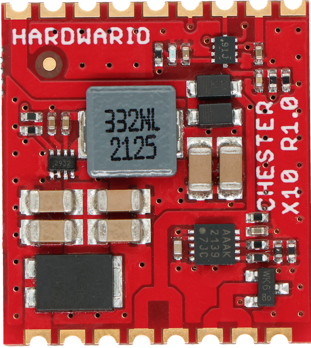
CHESTER-X10 powers the CHESTER mainboard from an external 5-28 VDC line on VIN and keeps it running when that supply fails. The on-board TPS62933 step-down converter produces a fixed 5 V rail, which both powers the mainboard and supplies the MCP73833 charger for a single-cell Li-Po / Li-Ion battery. The step-down output and the battery are diode-OR'd (Schottky PMEG6010ELR) onto the mainboard's supply, so while VIN is present the mainboard runs from the 5 V rail and the battery charges, and if VIN is lost the battery seamlessly takes over. A Schottky diode (PMEG060T030ELPEZ) protects the DC input.
An on-board TLA2024 12-bit ADC, read over I²C, measures the input voltage (VIN) and the battery voltage (BAT+) through precision dividers, so firmware can monitor the DC input and the battery state of charge. The module ships with a protected single-cell Li-Po battery and charges it at 450 mA.
Key Features
- Backup Power: Diode-OR between the DC input and the battery keeps the CHESTER mainboard powered if the external supply fails.
- Wide DC Input: External 5-28 VDC on VIN via the on-board TPS62933 step-down converter.
- Li-Po Charging: On-board MCP73833 charger for a single-cell Li-Po / Li-Ion battery at 450 mA.
- Battery Included: Protected single-cell 3.7 V / 2000 mAh Li-Po battery in the box.
- On-board Voltage Monitoring: 12-bit I²C ADC (TLA2024) measures the input and battery voltage.
- Input Protection: Schottky diode on the DC input.
- I²C Host Interface: Connects to the CHESTER mainboard over the standard I²C bus.
Typical Applications
- Uninterruptible Operation: Keep a CHESTER node running through mains or DC-supply outages.
- Remote & Off-Grid Sites: Buffer an intermittent DC source, such as a solar or harvested-power feed.
- Externally Powered Installations: Run CHESTER from an industrial DC line with battery backup.
- Battery-Backed Monitoring: Applications that need to track both the input voltage and the battery state of charge.
Technical Specifications
| Parameter | Value |
|---|---|
| Module Type | Backup power supply with single-cell Li-Po charger |
| Power Input (VIN) | 5-28 VDC |
| Power Output | Fixed 5 V, powers the CHESTER mainboard |
| Battery Type | Single-cell Li-Po / Li-Ion, 3.7 V, with integrated protection circuit |
| Charging Current | 450 mA |
| Min. Recommended Battery Capacity | 1000 mAh |
| Voltage Monitoring | On-board 12-bit I²C ADC (TLA2024), measures VIN and battery voltage |
| Host Interface | I²C |
| Included Battery | LP103454-PCM-LD, 3.7 V / 2000 mAh (56.0 × 34.5 × 10.3 mm) |
| Board Interface | Castellated holes on two opposite edges, soldered to the CHESTER mainboard |
| Hardware Revision | R1.1 |
Key Components
| Component | Part Number | Description |
|---|---|---|
| Step-Down Converter | TPS62933 | Step-down converter, 5-28 VDC input, 5 V output |
| Battery Charger | MCP73833 | Single-cell Li-Po / Li-Ion linear charger (450 mA) |
| Voltage-Monitoring ADC | TLA2024 | 12-bit 4-channel I²C ADC (address 0x49); measures VIN and battery voltage |
| Input Protection | PMEG060T030ELPEZ / PMEG6010ELR | Schottky barrier diodes (input protection and power-path OR-ing) |
Pin Configuration
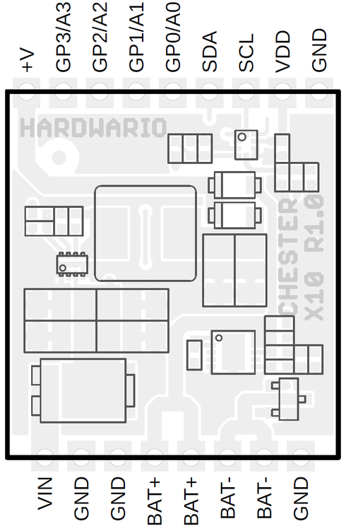
The module uses a standardized header layout compatible with CHESTER extension slots.
The pin configuration shown is for the CHESTER-M CGLS mainboard.
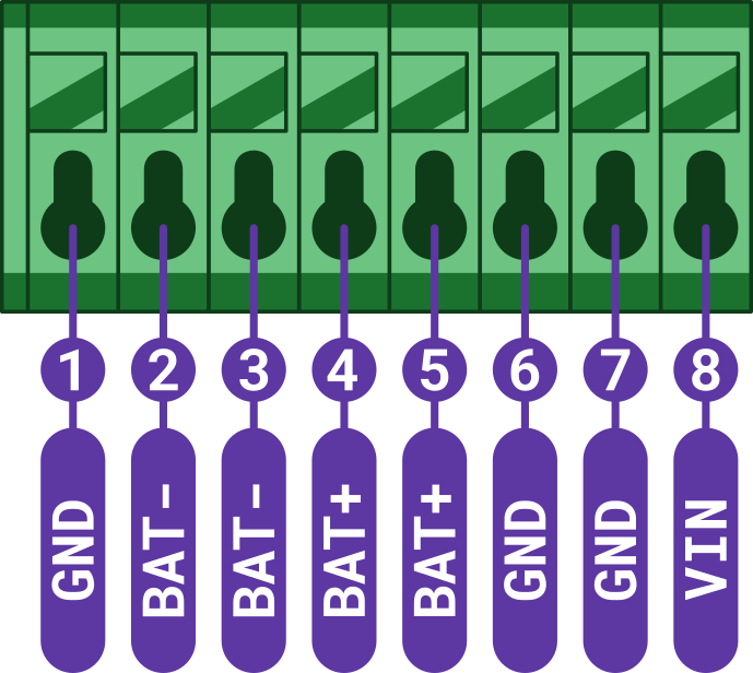
CHESTER-X10 Connector Pinout
| Pin | Signal | Type | Description |
|---|---|---|---|
| 1 | GND | Ground | System ground reference |
| 2 | BAT- | Battery | Battery negative terminal (*) |
| 3 | BAT- | Battery | Battery negative terminal (*) |
| 4 | BAT+ | Battery | Battery positive terminal (*) |
| 5 | BAT+ | Battery | Battery positive terminal (*) |
| 6 | GND | Ground | System ground reference |
| 7 | GND | Ground | System ground reference |
| 8 | VIN | Power Input | External DC supply input (5-28 VDC) |
*Note: Use only a single-cell 3.7 V Li-Po (or Li-Ion) battery with an integrated protection circuit. Do not short-circuit the battery! The two BAT- and the two BAT+ pins are internally connected (doubled for current capacity).
CHESTER-X10 powers the CHESTER mainboard through the module slot. An external 5-28 VDC supply on VIN (Pin 8) feeds the on-board TPS62933 step-down converter, whose fixed 5 V output powers the mainboard and charges the battery connected to BAT+ / BAT-. If the external supply is lost, the battery keeps the mainboard powered.
Host Interface (I²C)
CHESTER-X10 communicates with the CHESTER mainboard over the standard I²C bus. The on-board TLA2024 ADC sits at I²C address 0x49 and lets firmware read the input and battery voltage:
| ADC channel | Measured signal | Divider |
|---|---|---|
| AIN0 | VIN (input voltage) | 330 kΩ / 22 kΩ |
| AIN1 | BAT+ (battery voltage) | 1 MΩ / 1 MΩ |
Battery & Power Connection
Connect the external DC supply to VIN (Pin 8) and GND (Pin 1, 6, or 7), and connect a protected single-cell Li-Po / Li-Ion battery to BAT+ (Pin 4 or 5) and BAT- (Pin 2 or 3).
Use only a single-cell 3.7 V Li-Po / Li-Ion battery with an integrated protection circuit, and never short-circuit the battery. A battery capacity of at least 1000 mAh is recommended.
While the external supply is connected, the mainboard runs from the 5 V step-down output and the battery charges at 450 mA. If the external supply is disconnected or fails, the battery continues to power the mainboard through the module's power-path diodes, providing uninterrupted backup power.
Enclosure Feed-Through
Two options bring the DC-input cable into the enclosure:
- Cable gland (default): route the DC conductors through a cable gland in the enclosure wall and wire them to VIN and GND.
- Panel-mount connector (on request): an external connector in the enclosure wall lets the user plug in the DC supply, with no loose wiring inside. Available on request.
Compatible CHESTER Configurations
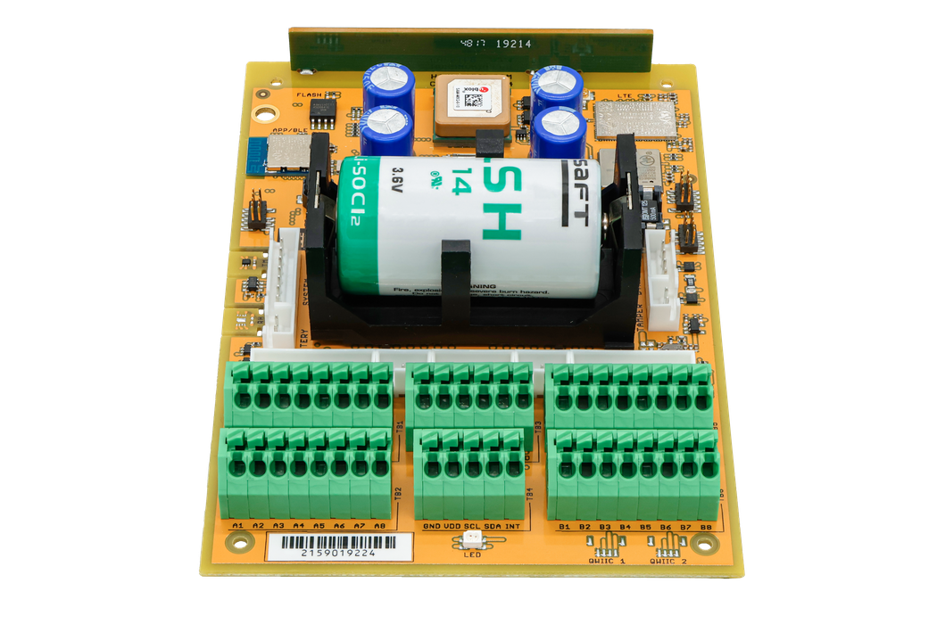
The CHESTER-X10 module can be used with various CHESTER mainboard configurations. Below are examples of compatible setups:
CHESTER-M (CGLS)
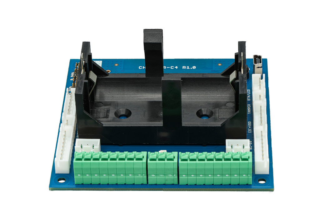
CHESTER-C4
CHESTER SDK usage
CHESTER-X10 can be used as part of the CHESTER SDK using the ctr_x10 shield, or the hardware-chester-x10 Project Generator feature.
Schematic Diagrams
The complete schematic, covering the power supply and charger, and the voltage-monitoring ADC, is available as a PDF:
Module Drawing