CHESTER-C1
This article describes the CHESTER-C1 carrier board.

Module Overview
CHESTER-C1 is a carrier board for CHESTER-M implementing:
- 4x digital/analog inputs terminal
- 2x power relay
- RS-485 interfaces terminal
- Two 1-Wire terminals
- DC/DC converter
- Battery holder for 4x C-cell sized 3.6V batteries
CHESTER-C1 fits with the Takachi WP20-28-5Cx enclosure.
Technical Specification
- Input DC voltage range (VIN): 8-36 V
- Supported C size battery: 1 x Saft LSH14 or 1 x Saft LS26500*
- Up to 4 x C size or 3 x D size battery on request (Saft LSH20 or LS33000)
- Nominal battery voltage: 3.6 V
- Battery idle current consumption <2 μA (without CHESTER-M)
* Saft LS26500 cannot be used with CHESTER-M-E variant (without supercapacitors).
For more details see Ordering Codes.
Module drawing
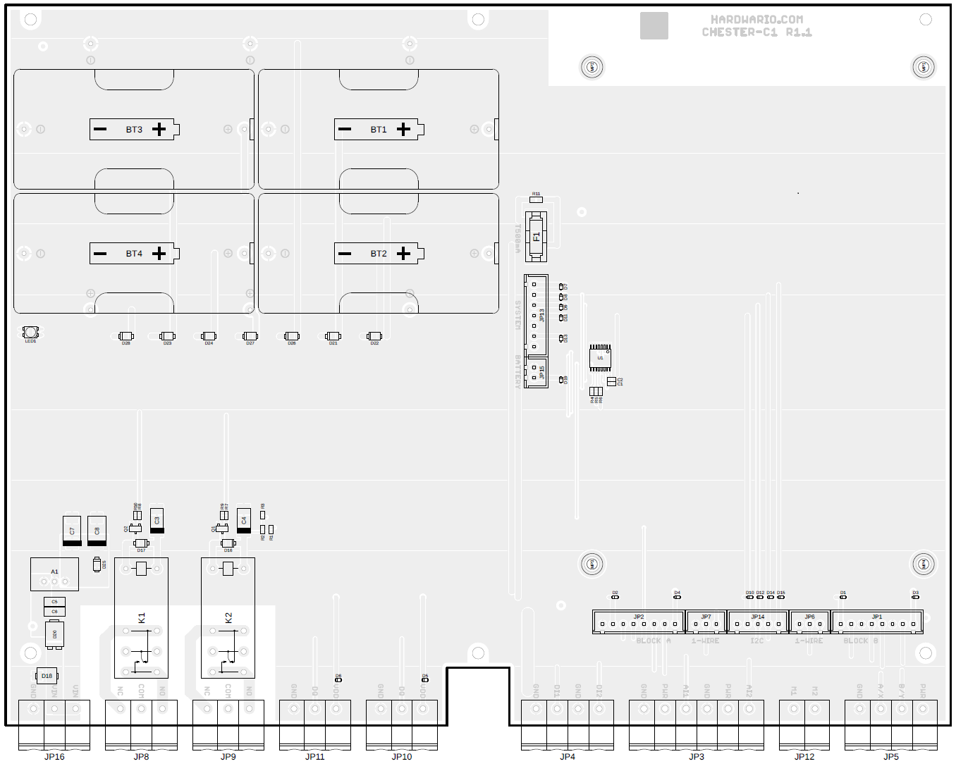
Inputs and outputs overview
| Position | Name | Signal Description |
|---|---|---|
| JP16 | VIN POWER | DC power supply input (VIN 8-36 V) |
| JP8 | RELAY 1 | Relay 1 power output |
| JP9 | RELAY 2 | Relay 2 power output |
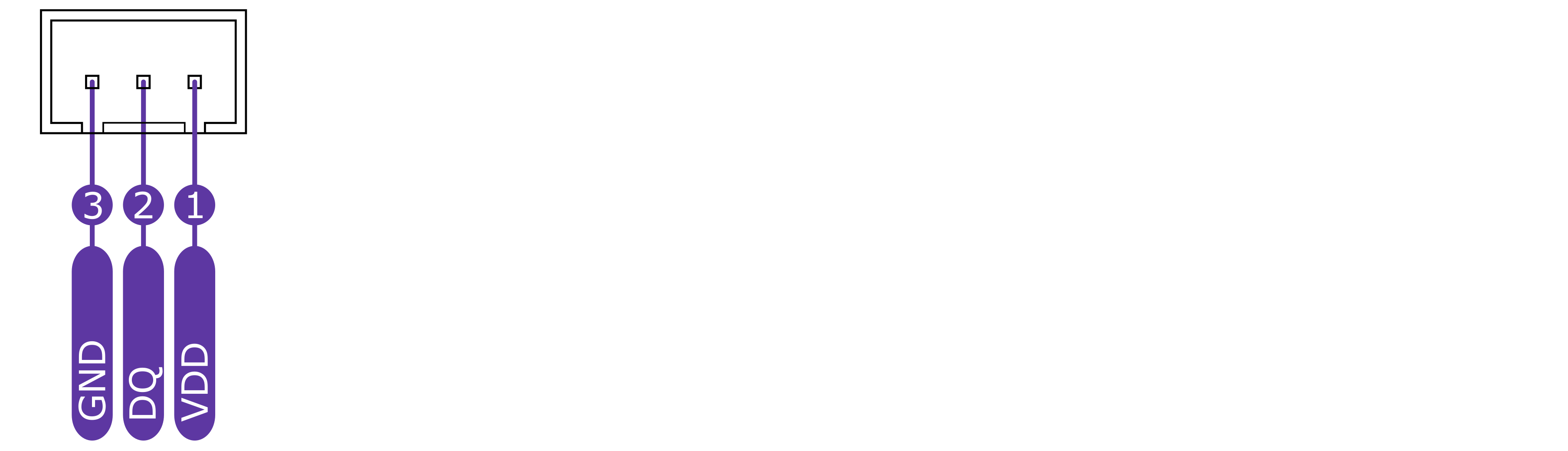
| JP11 | 1-WIRE | 1-Wire 3-pin terminal |
| JP10 | 1-WIRE | 1-Wire 3-pin terminal |
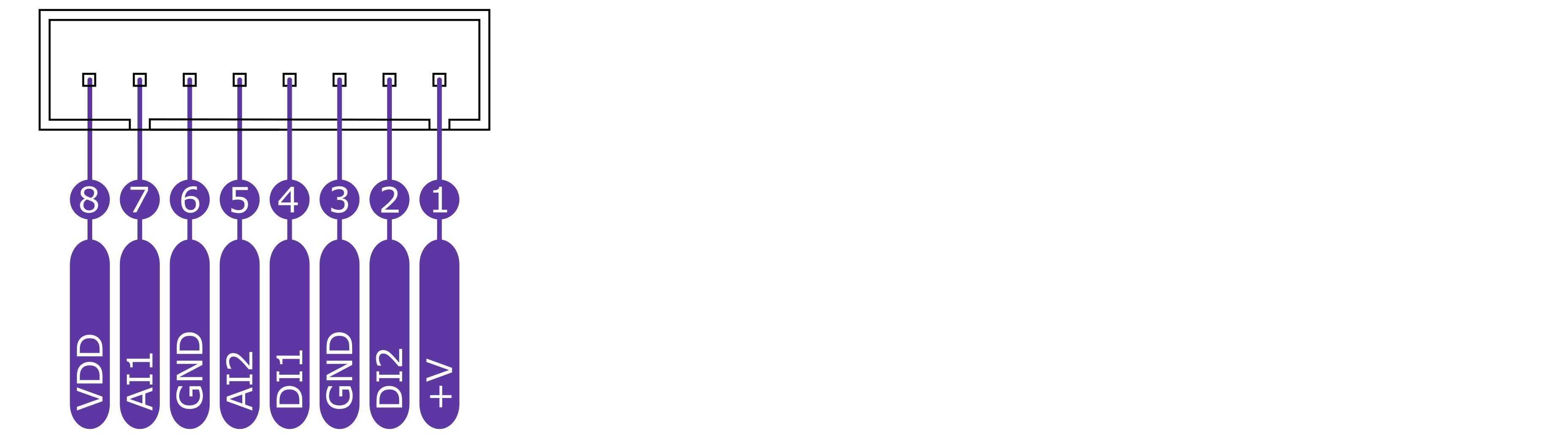
| JP4 | DIGITAL | 2 x digital I/O |
| JP3 | ANALOG | 2 x analog I/O + 2 x VIN |
| JP12 | NA | Not used |
| BT1-BT4 | BATTERY | 4 x C size holder for 3.6 primary cell* |
| BT5-BT7 | BATTERY | 3 x D size holder for 3.6 primary cell* |
* CHESTER-X SLOT A is by default occupied with integrated module CHESTER-X1
** Use the BYPASS BUTTON to initiate start from the battery without DC input power supply
Pinout Description
Block A Connectors

1-Wire Connectors
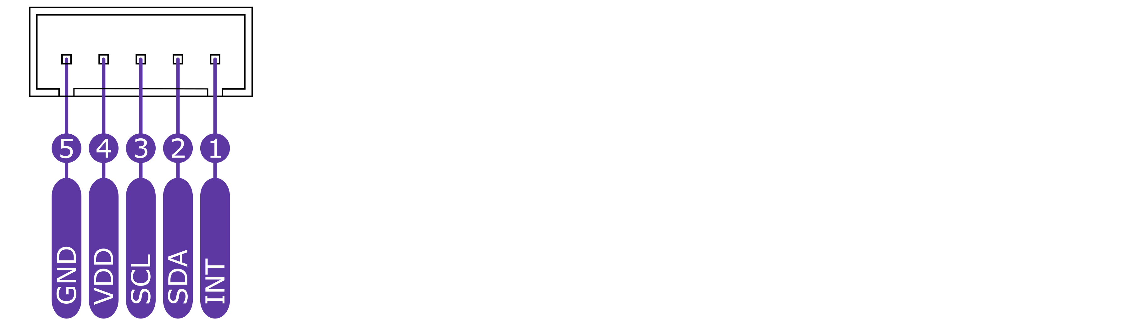
I2C Connector
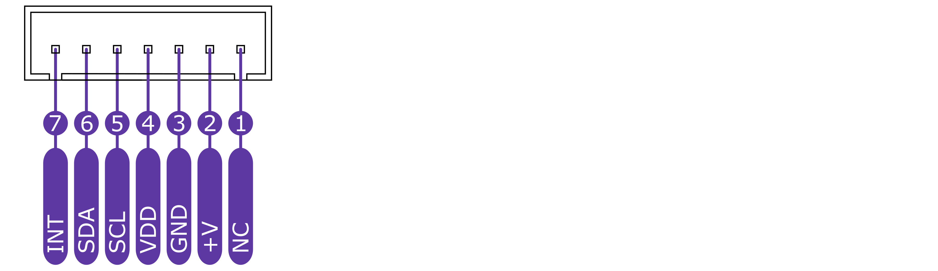
SYSTEM Connector
Block B Connectors
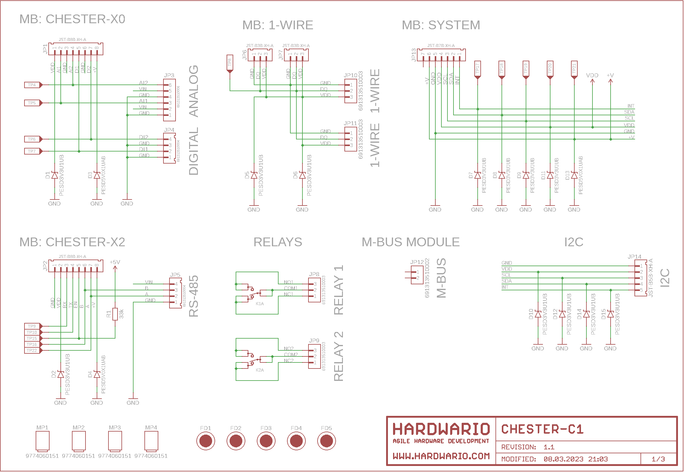
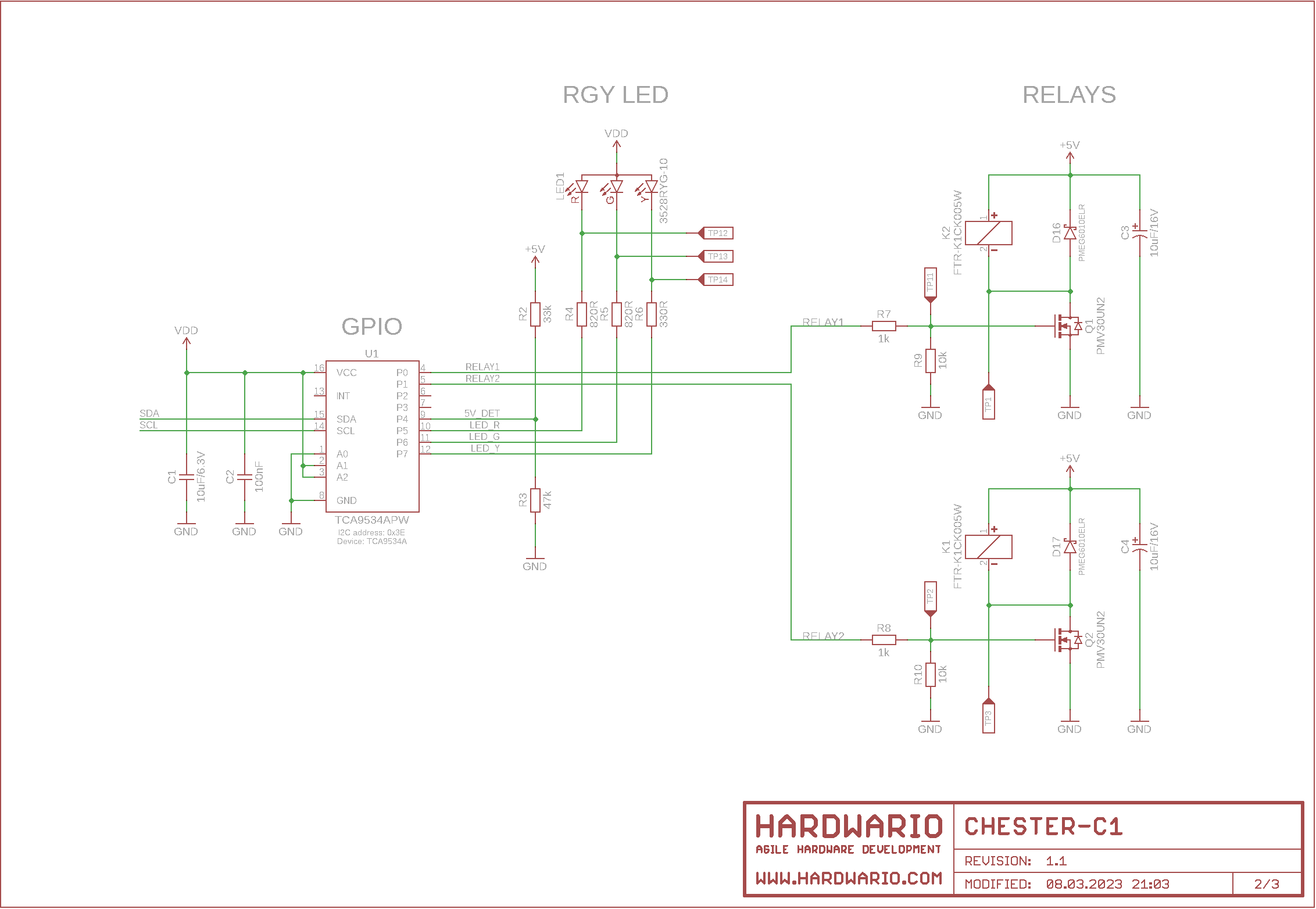
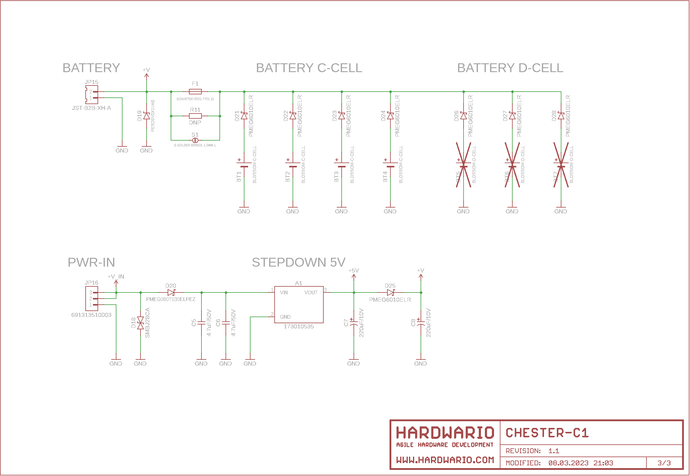
Schematic Diagram
A schematic diagram is useful if you program low-level hardware-related code or if you're just curious about how the system is designed.