CHESTER-X13
This article describes the CHESTER-X13 extension module.
Module Overview
CHESTER-X13 provides a CAN Bus interface with support for CAN FD standard. It also comes with a built-in step-down with support of up to 28 V.
CHESTER Pin Configuration Diagram
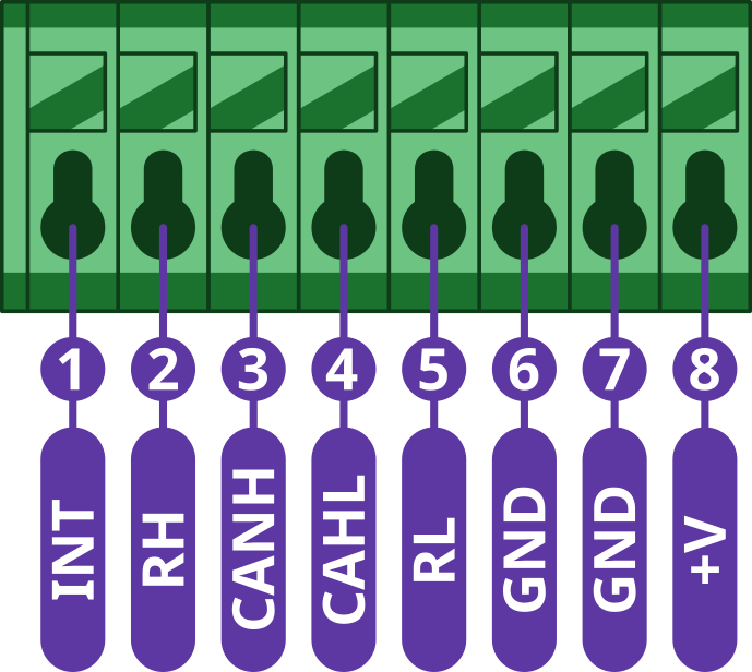
Pin Configuration and Functions
| Position | Signal Name | Signal Description |
|---|---|---|
| 1 | INT | Interrupt signal |
| 2 | RH | CAN termination resistor |
| 3 | CANH | Bus input/output |
| 4 | CANL | Bus input/output |
| 5 | RL | CAN termination resistor |
| 6 | GND | System ground signal |
| 7 | GND | System ground signal |
| 8 | +VIN | Step-down input voltage |
Interrupt Pin
The module provides an interrupt output (pin 1), which needs to be connected to the INT pin on the CHESTER mainboard.
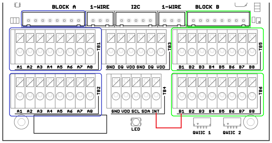
- Example of interrupt connection for module in slot B
Termination Resistors
CAN bus is required to be terminated by placing a 120 Ohm resistor between the High and Low lines at both ends of the bus. CHESTER-X13 provides these resistors, but they are disconnected by default (as they aren't needed for a normal CAN node). The terminating resistors can be connected by connecting CANH to RH and CANL to RL (for example using jumpers on the JST connector.
CHESTER SDK usage
CHESTER-X13 can be used as part of the CHESTER SDK using the ctr_x13_a and ctr_x13_b shields, or hardware-chester-x13-a and hardware-chester-x13-b Project Generator features.
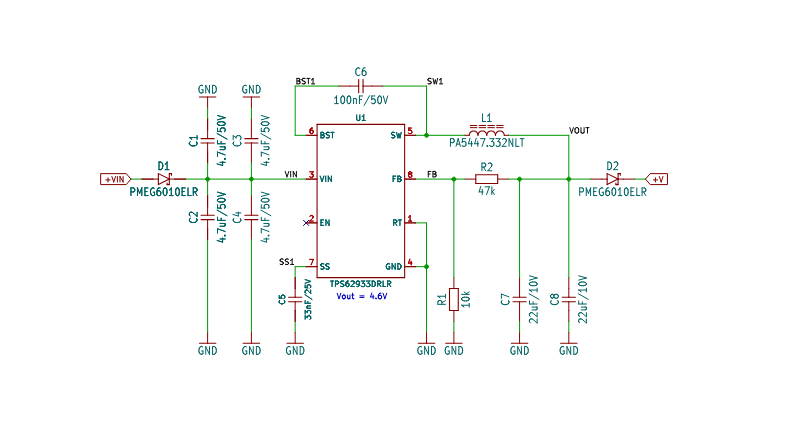
Schematic diagram
A schematic diagram is useful if you program low-level hardware-related code or if you're just curious about how the system is designed.

Module Drawing
