CHESTER-X2
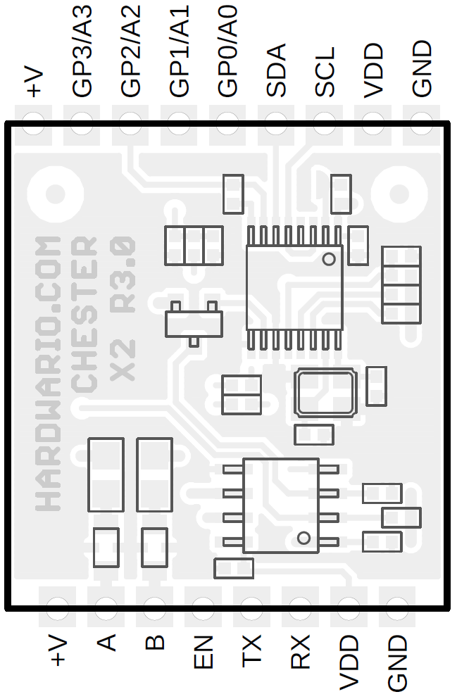
This article describes the CHESTER-X2 extension module.
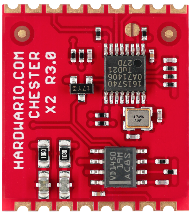
Module Overview
CHESTER-X2 provides TTL/UART interface and RS-485 interface (e.g., for Modbus communication).
CHESTER Pin Configuration Diagram
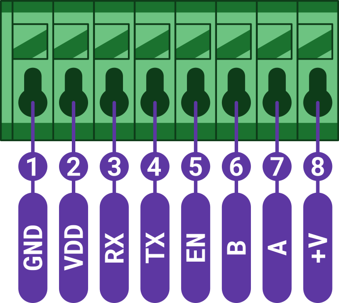
Pin Configuration and Functions
| Position | Signal Name | Signal Description |
|---|---|---|
| 1 | GND | System ground signal |
| 2 | VDD | System VDD rail 3.0 V |
| 3 | RX | UART receiver input |
| 4 | TX | UART transmitter output |
| 5 | EN | Enable input |
| 6 | B | Bus input/output |
| 7 | A | Bus input/output |
| 8 | +V | System positive rail (*) |
*Note: The system positive rail voltage depends on CHESTER power supply option.
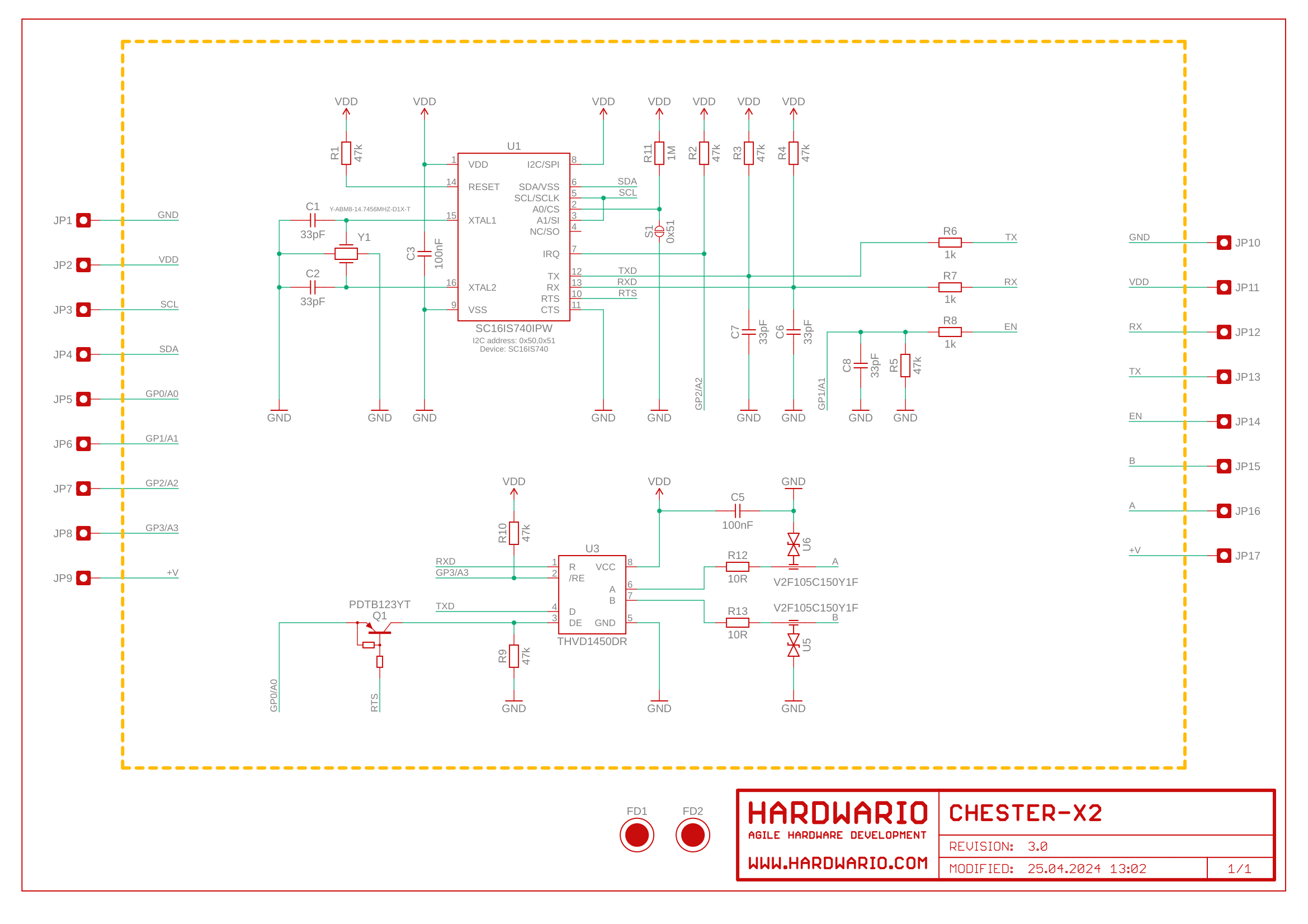
Schematic diagram
A schematic diagram is useful if you program low-level hardware-related code or if you're just curious about how the system is designed.
Module Drawing