CHESTER-X1
This article describes the CHESTER-X1 extension module.
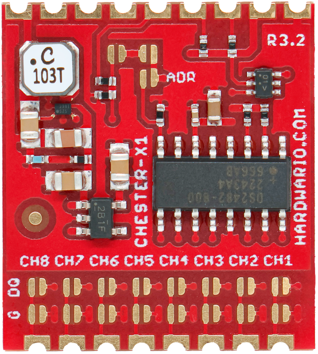
Module Overview
CHESTER-X1 provides 8 independent 1-Wire channels allowing to connect digital sensors ( e.g. Dallas DS18B20) or any other 1-Wire peripheries. The module implements Maxim DS2482S-800+ interface and also 5V boost converter to support 5V 1-Wire peripheries.
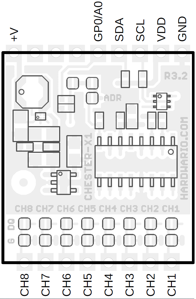
CHESTER Pin Configuration Diagram
Pin Configuration and Functions
| Position | Signal Name | Signal Description |
|---|---|---|
| 1 | CH1 | Channel 1 |
| 2 | CH2 | Channel 2 |
| 3 | CH3 | Channel 3 |
| 4 | CH4 | Channel 4 |
| 5 | CH5 | Channel 5 |
| 6 | CH6 | Channel 6 |
| 7 | CH7 | Channel 7 |
| 8 | CH8 | Channel 8 |
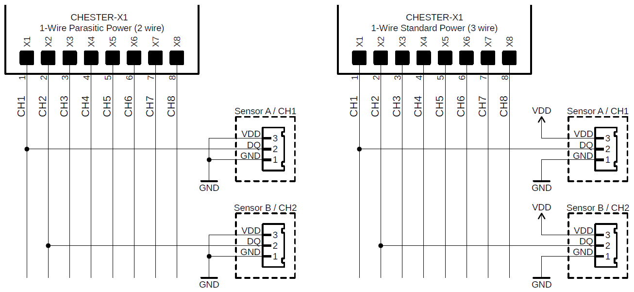
1-Wire Parasitic Power Connection
CHESTER-X1 supports connection using parasitic powering method. In that case only 2 wires are necessary. In the parasitic mode 5.0V power supply is used. Standard 3 wire connection powering from VDD supports only 3.0V peripheries. This figure shows parasitic and standard powering method:
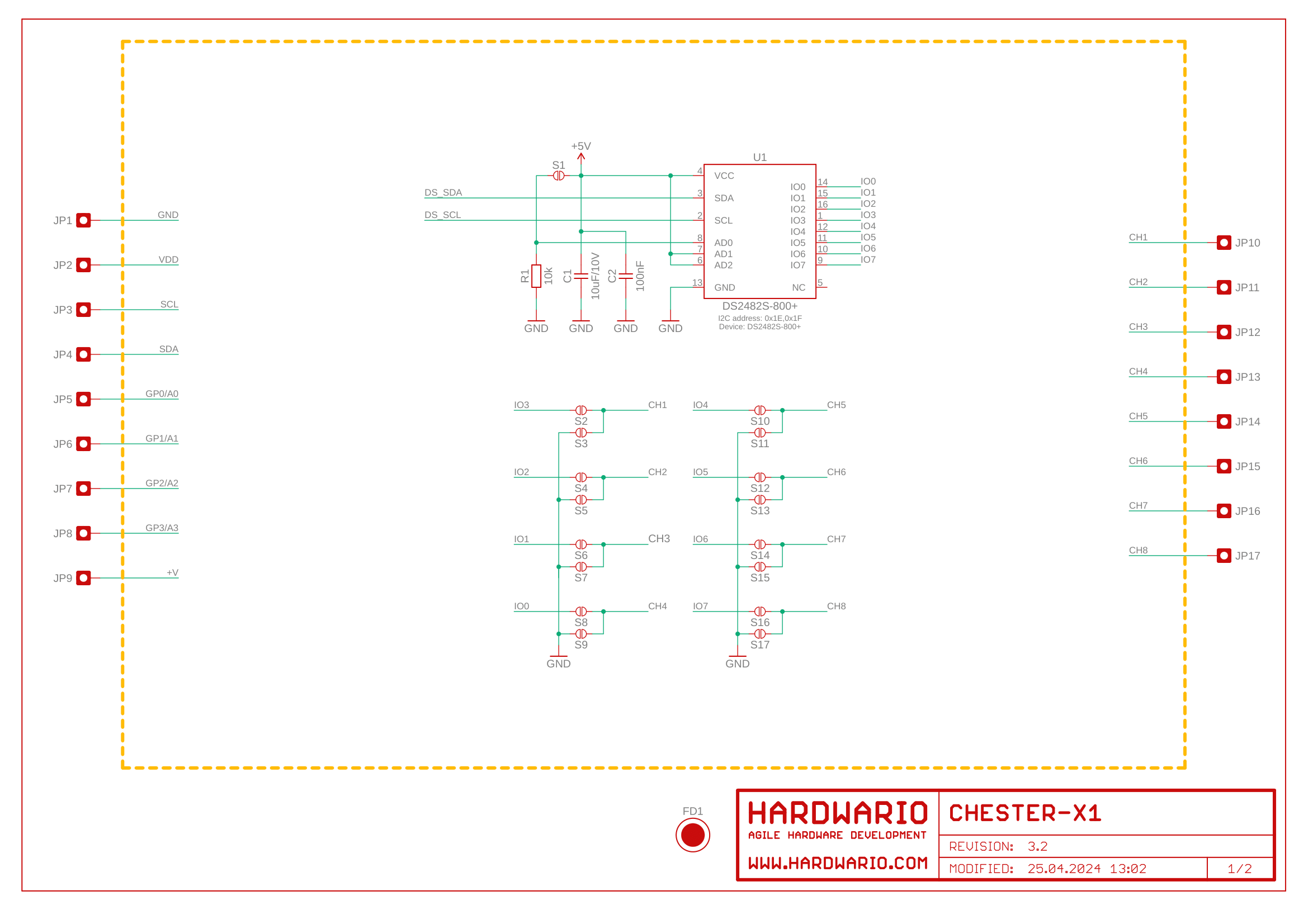
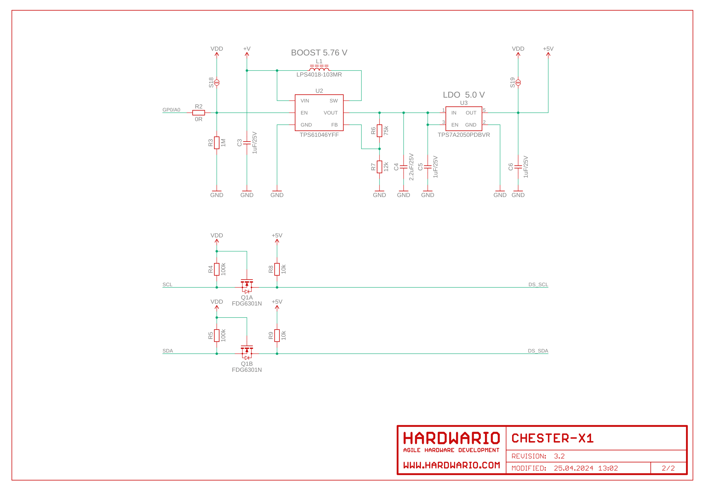
Schematic diagram
A schematic diagram is useful if you program low-level hardware-related code or if you're just curious about how the system is designed.
Module Drawing