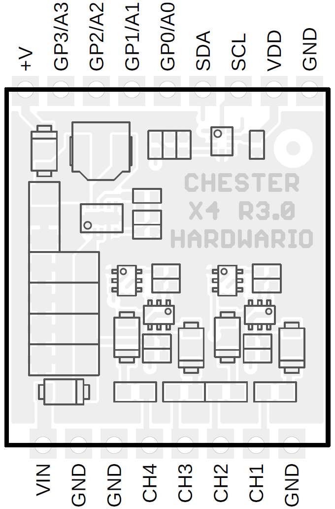
CHESTER-X4
This article describes the CHESTER-X4 extension module.

Module Overview
CHESTER-X4 implements a step-down DC/DC converter providing power from an external 6-28 VDC line (VIN). It allows also the input voltage measurement. This module has also 4 P-MOS switches allowing to supply of independent loads from VIN voltage input.
Output Protection
Each of the four outputs has a resetable PTC fuse protection (femtoSMDC005F). Each output can reliably supply 50 mA of constant current. The trip current is around 150 mA.
CHESTER Pin Configuration Diagram
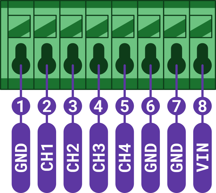
Pin Configuration and Functions
| Position | Signal Name | Signal Description |
|---|---|---|
| 1 | GND | System ground signal |
| 2 | CH1 | Channel 1 voltage output switch |
| 3 | CH2 | Channel 2 voltage output switch |
| 4 | CH3 | Channel 3 voltage output switch |
| 5 | CH4 | Channel 3 voltage output switch |
| 6 | GND | System ground signal |
| 7 | GND | System ground signal |
| 8 | VIN | DC power supply voltage input (6-28V) |
Schematic diagram
A schematic diagram is useful if you program low-level hardware-related code or if you're just curious about how the system is designed.

Module Drawing