CHESTER-K1

CHESTER Pin Configuration Diagram
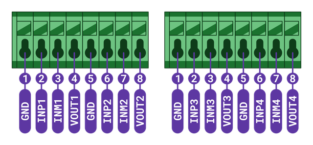
The extension module CHESTER-K1 use both slots A and B. So you use the corresponding terminals A1 to A8 (left terminal block in the picture above) and B1 to B8 (right terminal block in the picture above).
Current Transformer Signals
| Signal | Wire color |
|---|---|
| GND | Black |
| INP | White |
| INM | Yellow |
| VOUT | Red |
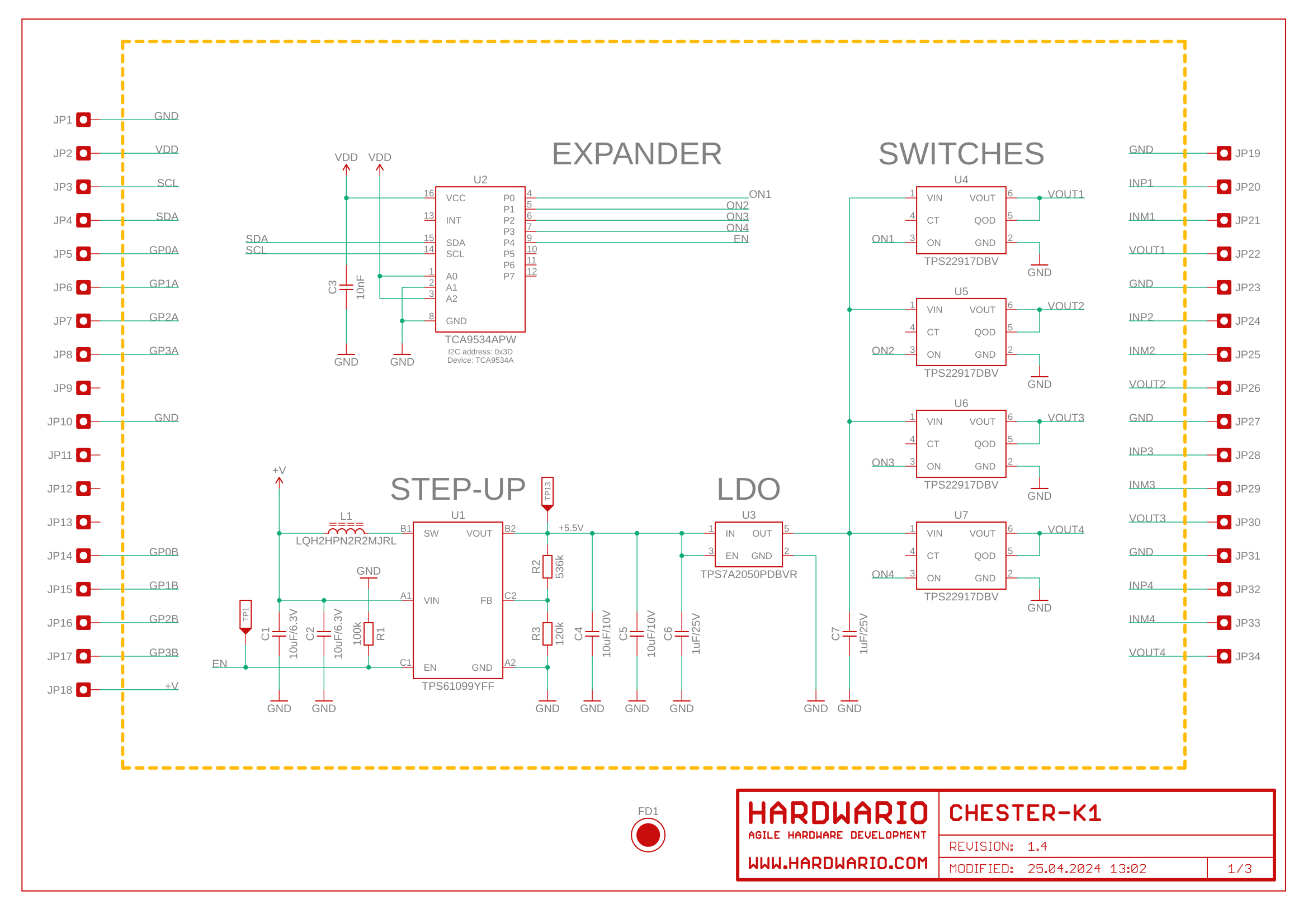
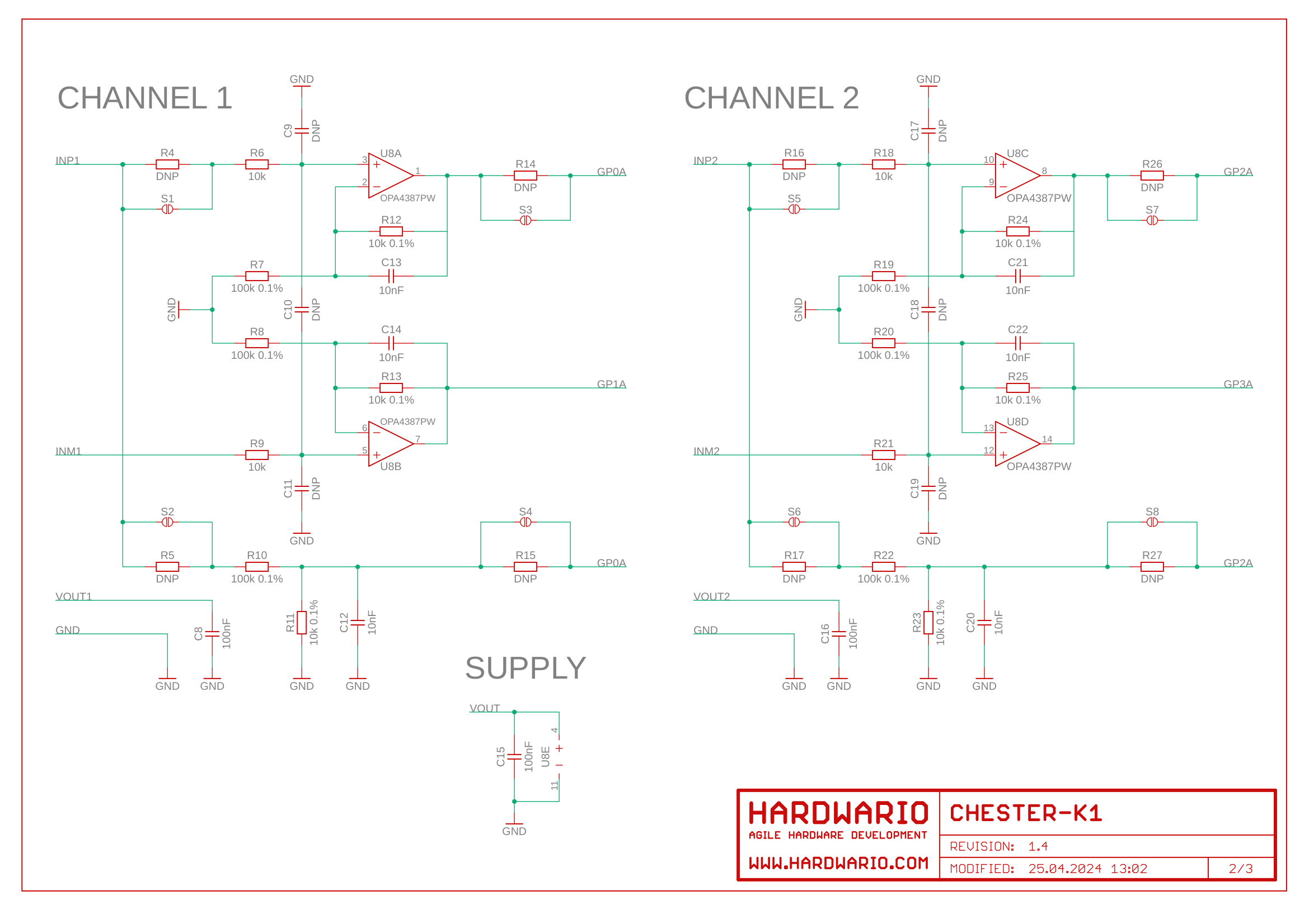
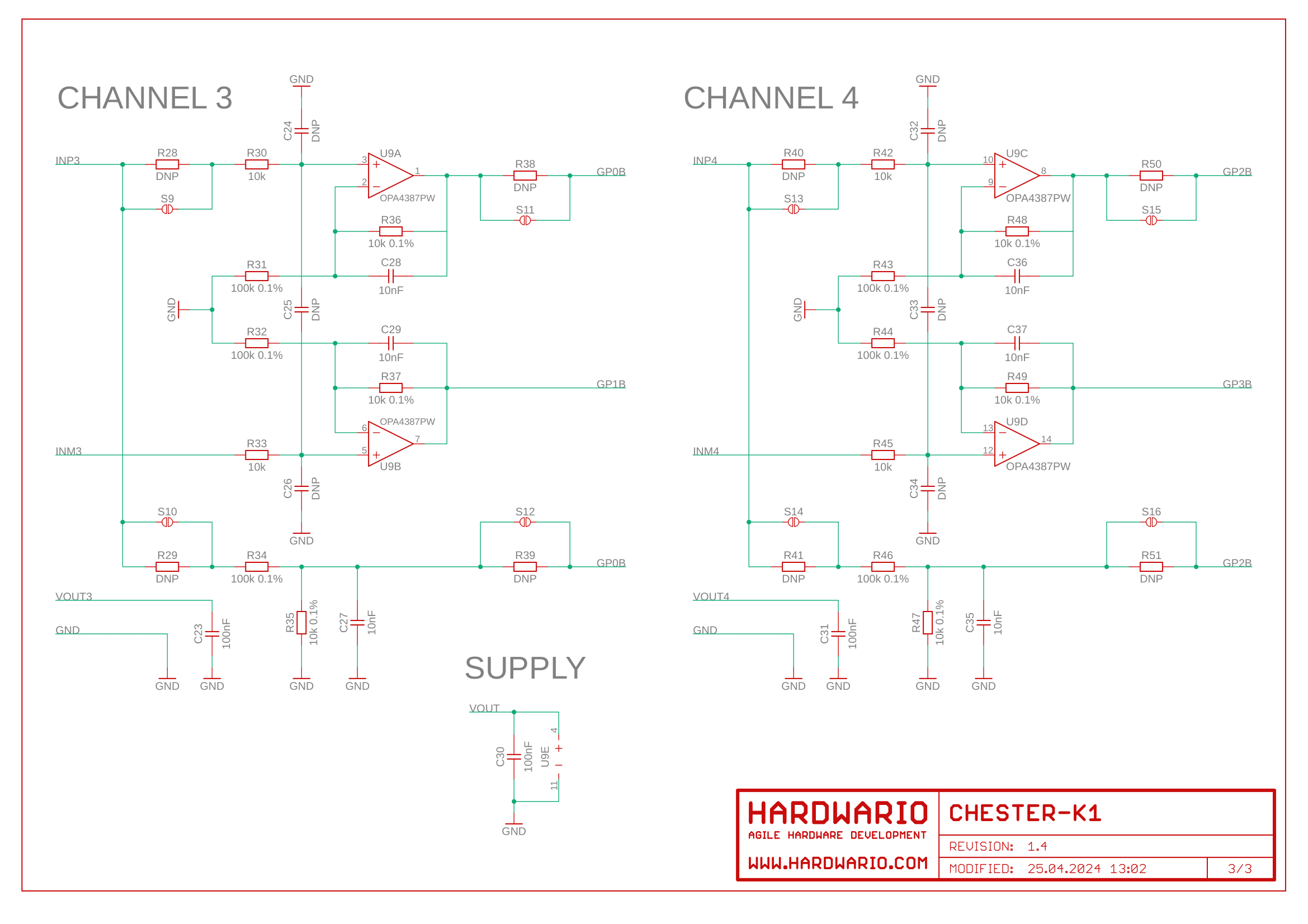
Schematic diagram
A schematic diagram is useful if you program low-level hardware-related code or if you're just curious about how the system is designed.