CHESTER-X12
The CHESTER-X12 is an extension module for the CHESTER platform that provides a serial communication interface via the RS-232 standard.
The module features an I2C to UART bridge controller (SC16IS740IPW) and an RS-232 level shifter (MAX3226EEUE+), allowing connection to industrial serial devices and equipment. It includes a dedicated power input (5–28 V) with an efficient DC-DC converter (TPS62933) for powering external RS-232 devices, making it suitable for industrial automation, building management systems, and legacy equipment integration.

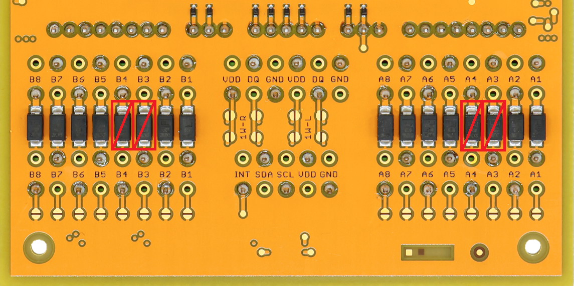
The RS-232 transceiver uses negative voltage levels. CHESTER must have modified ESD protection on inputs for signals A3 and A4 on slot A, or B3 and B4 on slot B. The standard unidirectional TVS diodes (SMA6J28A) must be replaced with bidirectional ones (SMA6J28CA). If ESD protection is not required, these diodes can be removed.
Key Features
- RS-232 Interface: Full-duplex communication with industrial-grade levels.
- I2C to UART Bridge: Based on SC16IS740IPW for seamless integration with the CHESTER mainboard.
- Wide Input Voltage: 5–28 V DC input range for powering external devices.
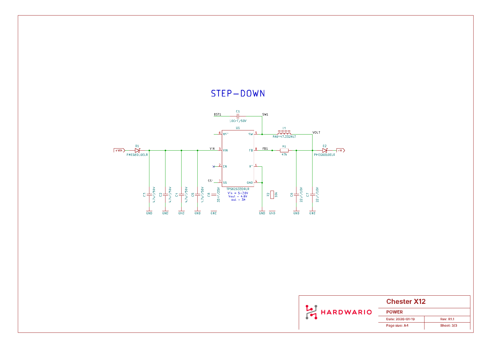
- Efficient Power: Integrated DC-DC converter (TPS62933) for stable power delivery.
- Protection: ±15kV ESD protection on RS-232 I/O pins.
- Flow Control: Hardware flow control support (RTS/CTS).
Typical Applications
- Industrial Sensors: Connection to sensors and controllers through the CHESTER platform.
- Legacy Equipment: Integration with existing RS-232 devices.
- Building Automation: HVAC systems, lighting control, and metering.
- Commercial: Point-of-Sale (POS) terminals and barcode scanners.
- Utilities: Serial console access and laboratory equipment interfaces.
Technical Specifications
| Parameter | Value |
|---|---|
| Interface Type | RS-232 |
| Protocol | Full-duplex asynchronous serial |
| Baud Rate | Up to 250 kbps (Transceiver limit) / 3 Mbps (Bridge limit) |
| Input Voltage (+VIN) | 5 to 28 V DC |
| Data Bits | 5, 6, 7, 8 |
| Stop Bits | 1, 1.5, 2 |
| Parity | None, Even, Odd, Mark, Space |
| Flow Control | Hardware (RTS/CTS), Software (XON/XOFF) |
| Connector | Standard 2.54 mm pitch header (Soldered) |
Key Components
| Component | Part Number | Description |
|---|---|---|
| I2C to UART Bridge | SC16IS740IPW | Single UART with I2C-bus/SPI interface, 64-byte FIFO |
| RS-232 Transceiver | MAX3226EEUE+ | True RS-232 levels, ±15kV ESD protection |
| DC-DC Converter | TPS62933 | Step-down converter, 5–28 V input, up to 3A output |
| Input Protection | PMEG6010ELRX | Schottky barrier diodes for input protection |
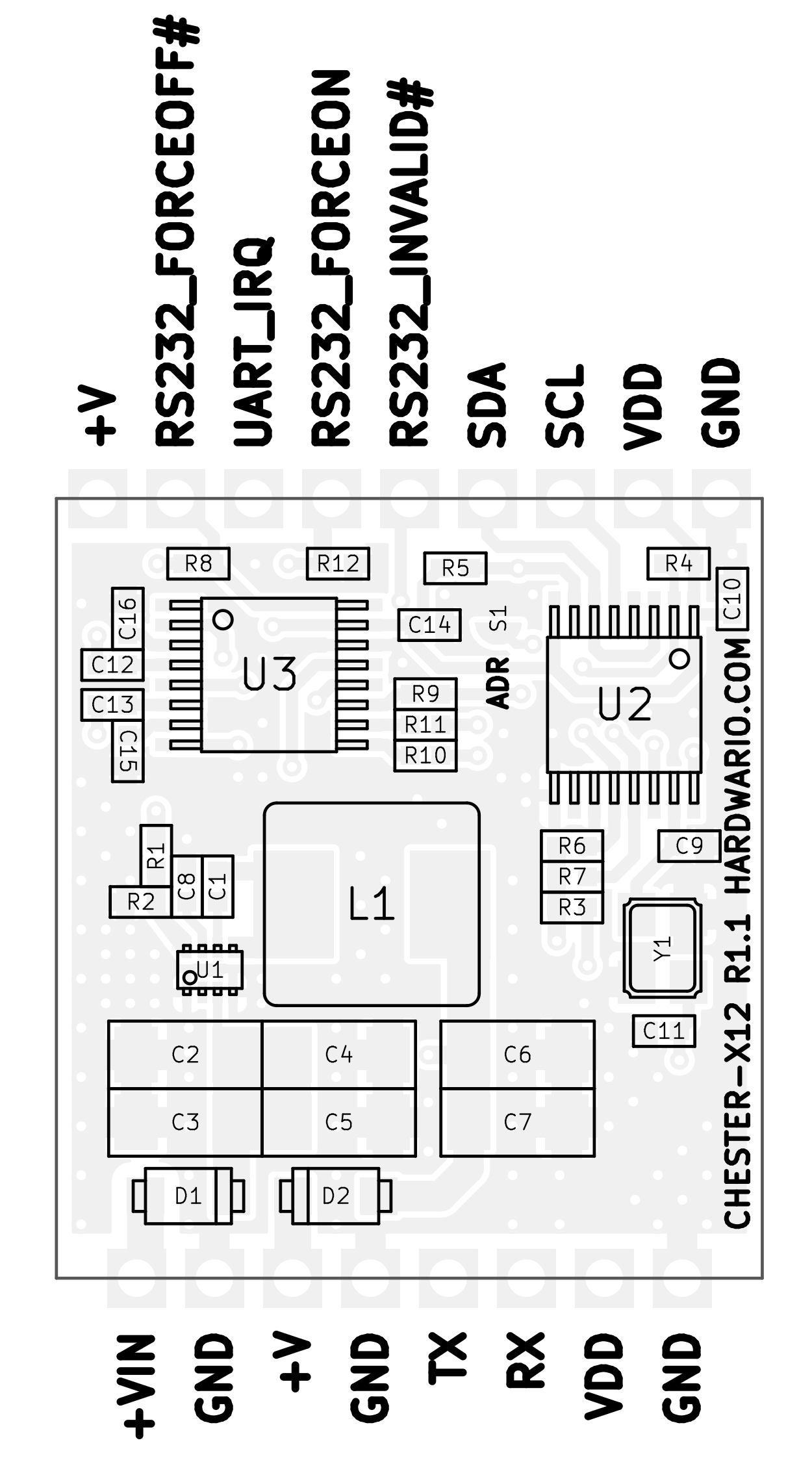
Pin Configuration
The module uses a standardized header layout compatible with CHESTER extension slots.
CHESTER-X12 Connector Pinout
| Pin | Signal | Type | Description |
|---|---|---|---|
| 1 | GND | Ground | Ground reference |
| 2 | +VIN | Power Input | External power input (5–28 V DC) |
| 3 | GND | Ground | Ground reference |
| 4 | +V | Power Output | Auxiliary power output (from DC-DC converter) |
| 5 | RX | Input | RS-232 Receive Data |
| 6 | TX | Output | RS-232 Transmit Data |
| 7 | GND | Ground | Ground reference |
| 8 | VDD | Power | 3.3 V supply from CHESTER mainboard |
The +VIN terminal (Pin 2) is used to power the DC-DC converter, which subsequently powers the external devices via the +V terminal (Pin 4). The logic of the module itself (UART bridge) is powered by VDD (Pin 8) from the CHESTER mainboard.
Compatible CHESTER Configurations
The CHESTER-X12 module can be used with various CHESTER mainboard configurations. Below are examples of compatible setups:
CHESTER-M (CGLS)

CHESTER-C4

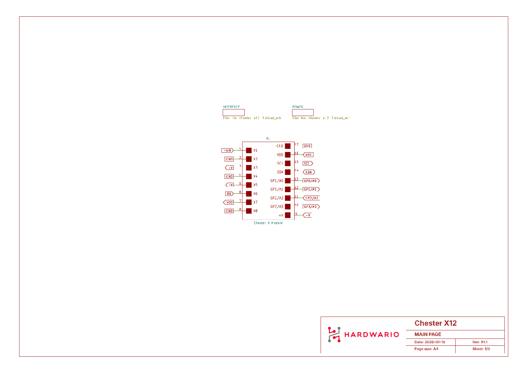
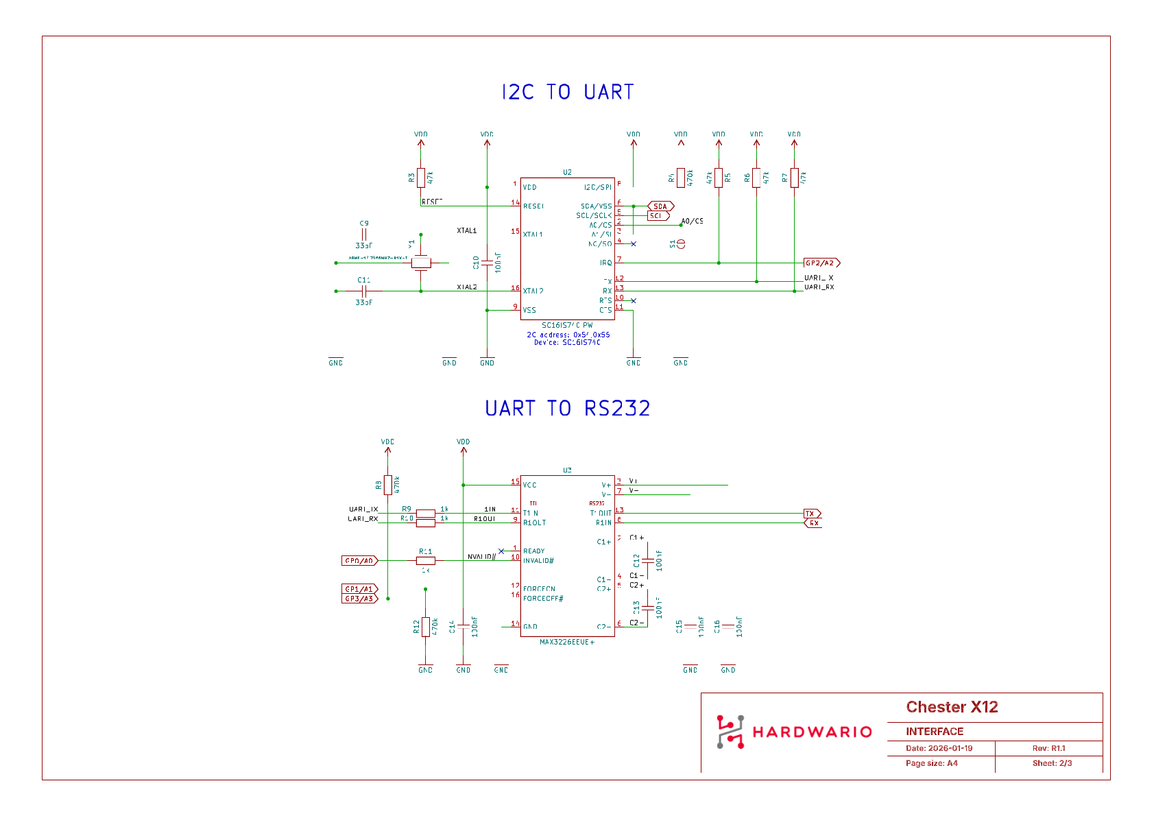
Schematic Diagrams
The following diagrams show the internal wiring of the module, including the system connection, interface logic, and power supply.
Main Page
Interface
Power Supply
Module Drawing