CHESTER-X5
This article describes the CHESTER-X5 extension module.
Module Overview
CHESTER-X5 implements two isolated voltage inputs. Each can measure voltage from -50 V to + 50 V.
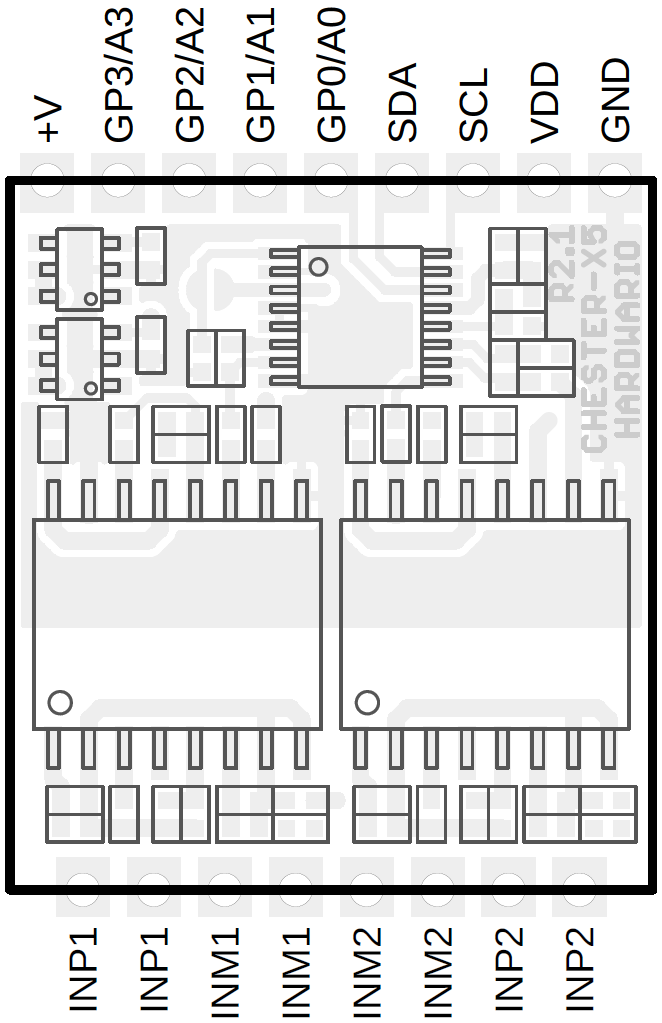
CHESTER Pin Configuration Diagram
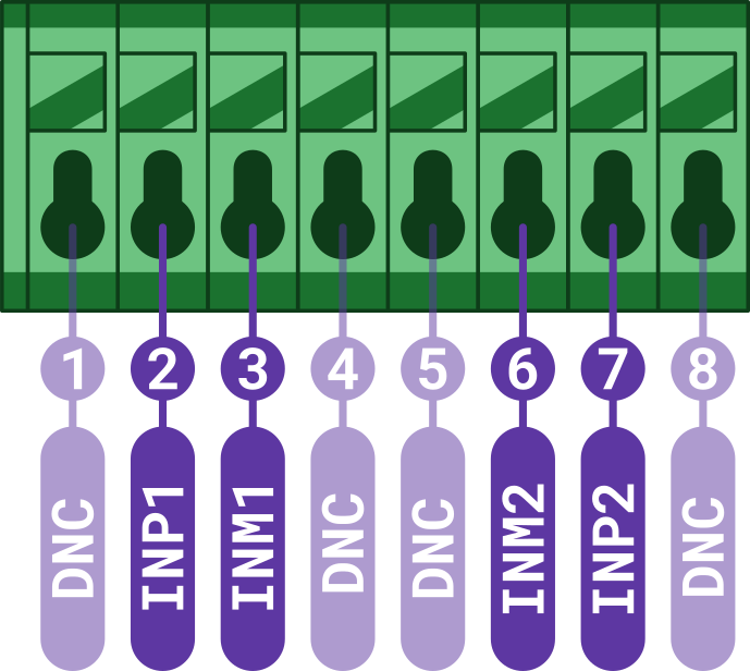
Pin Configuration and Functions
| Position | Signal Name | Signal Description |
|---|---|---|
| 1 | DNC | Reserved |
| 2 | INP1 | Channel 1 positive input |
| 3 | INM1 | Channel 1 negative input |
| 4 | DNC | Reserved |
| 5 | DNC | Reserved |
| 6 | INM2 | Channel 2 negative input |
| 7 | INP2 | Channel 2 positive input |
| 8 | DNC | Reserved |
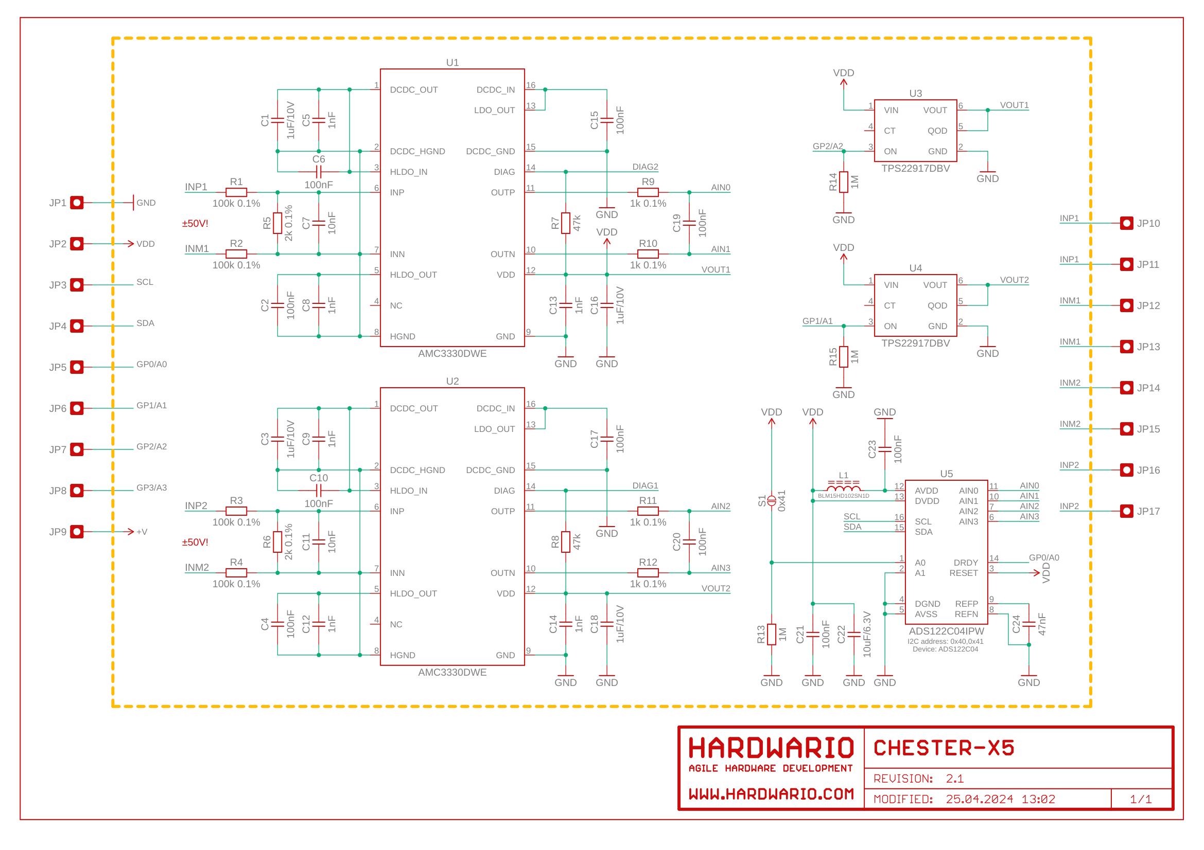
Schematic diagram
A schematic diagram is useful if you program low-level hardware-related code or if you're just curious about how the system is designed.
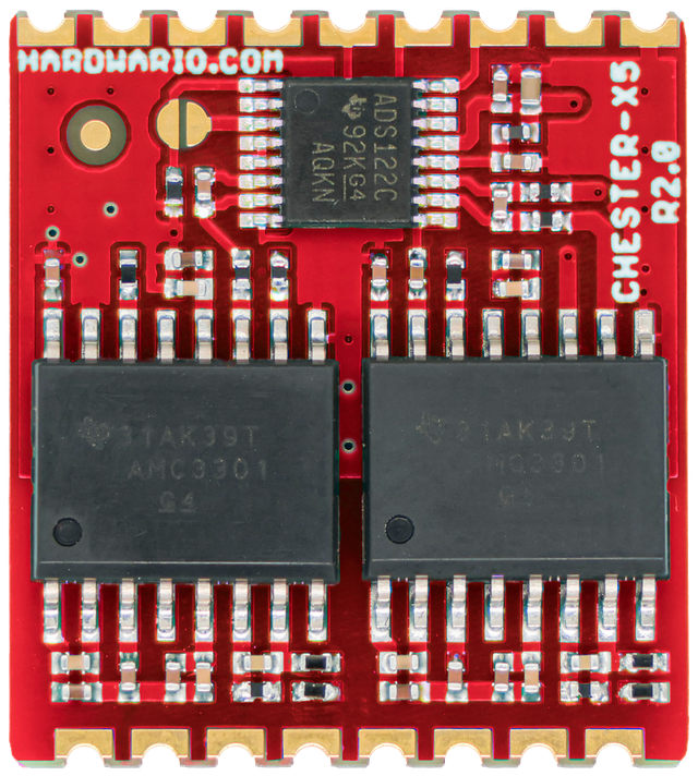
Module Drawing