CHESTER-X14
This article describes the CHESTER-X14 extension module.
Module Overview
CHESTER-X14 provides support for 10/100 Ethernet connectivity. It also comes with a built-in step-down with support of up to 28 V.
CHESTER Pin Configuration Diagram
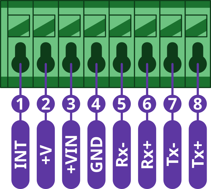
Pin Configuration and Functions
| Position | Signal Name | Signal Description |
|---|---|---|
| 1 | INT | Interrupt signal |
| 2 | +V | System positive rail (*) |
| 3 | +VIN | Step-down input voltage |
| 4 | GND | System ground signal |
| 5 | Rx- | Ethernet signal |
| 6 | Rx+ | Ethernet signal |
| 7 | Tx- | Ethernet signal |
| 8 | Tx+ | Ethernet signal |
*Note: The system positive rail voltage depends on CHESTER power supply option.
Interrupt Pin
The module provides an interrupt output (pin 1), which needs to be connected to the INT pin on the CHESTER mainboard.
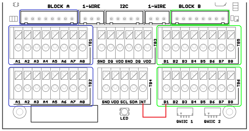
- Example of interrupt connection for module in slot B
CHESTER SDK usage
CHESTER-X14 can be used as part of the CHESTER SDK using the ctr_x14_a and ctr_x14_b shields, or hardware-chester-x14-a and hardware-chester-x14-b Project Generator features.
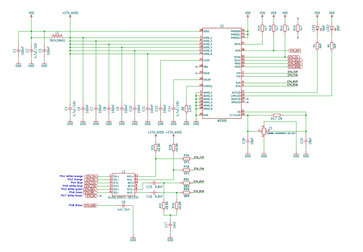
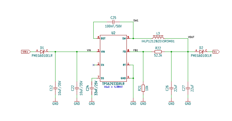
Schematic diagram
A schematic diagram is useful if you program low-level hardware-related code or if you're just curious about how the system is designed.
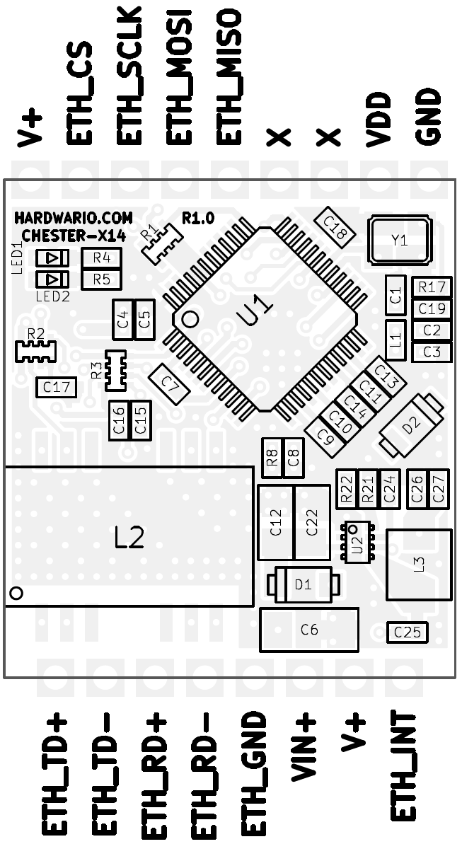
Module Drawing