CHESTER-X6
The CHESTER-X6 is a HARDWARIO S-Wire bus extension module for the CHESTER platform.
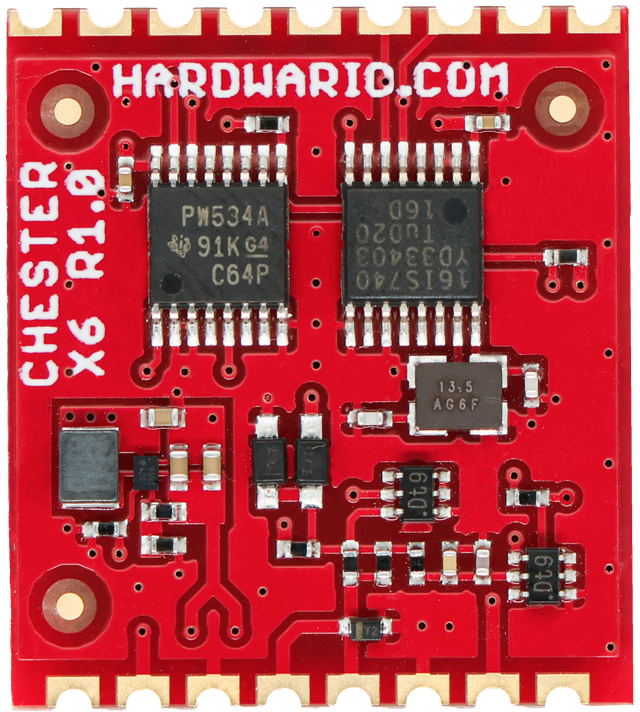
Module Overview
CHESTER-X6 connects low-power S-Wire peripherals to the CHESTER platform over a simple 3-wire link: +5 V, GND, and a single DATA line. The S-Wire protocol runs on a UART engine provided by an SC16IS740 I²C-to-UART bridge; a transistor line driver converts the bridge's UART signals to the single half-duplex 5 V DATA line, with ESD protection. The module is controlled entirely over I²C. There are two I²C devices: the UART bridge and a TCA9534A GPIO expander that switches the peripheral power, resets the bridge, and handles its interrupt.
An on-board boost converter (TPS61099) generates the regulated 5 V that powers the connected peripherals. Because it steps up from the CHESTER +V rail, the module can supply a clean 5 V to the peripherals even when the CHESTER runs from a battery. The 5 V output is switched on under I²C control (via the expander), so peripheral power can be turned off between reads to save energy.
Key Features
- HARDWARIO S-Wire Interface: Connects low-power S-Wire peripherals over a 3-wire link (+5 V, GND, DATA).
- I²C Controlled: Two I²C devices, the SC16IS740 UART bridge (0x4D) and the TCA9534A expander (0x39); no GP pins are used.
- On-board 5 V Boost: TPS61099 provides a regulated 5 V for the peripherals, even when the CHESTER runs from a battery.
- Switchable Peripheral Power: The 5 V output is enabled over I²C, so it can be turned off between reads.
- Protected DATA Line: Half-duplex single-wire driver with ESD protection.
Typical Applications
- S-Wire Peripherals: Connecting HARDWARIO S-Wire sensors and peripherals to a CHESTER node.
- Daisy-Chained Sensing: Wiring several S-Wire peripherals on one bus.
- Powered Remote Peripherals: Peripherals that need a regulated 5 V supply from a battery-powered node.
- Low-Power Peripheral Expansion: Adding a simple, low-pin-count peripheral bus to a CHESTER installation.
Technical Specifications
| Parameter | Value |
|---|---|
| Module Type | HARDWARIO S-Wire bus interface |
| Peripheral Interface | S-Wire (3-wire: +5 V, GND, DATA) |
| Data Line | Single half-duplex DATA line, ESD-protected |
| Host Interface | I²C (UART bridge 0x4D + GPIO expander 0x39) |
| Peripheral Power | Regulated 5.0 V (on-board boost), switchable over I²C |
| UART Bridge | SC16IS740IPW (13.56 MHz) |
| Logic Supply (VDD) | 3.0 V |
| Board Interface | Castellated holes on two opposite edges, soldered to the CHESTER mainboard |
| Hardware Revision | R1.0 |
Key Components
| Component | Part Number | Description |
|---|---|---|
| I²C-to-UART Bridge | SC16IS740IPW | Single UART with I²C interface (address 0x4D); the S-Wire UART engine |
| GPIO Expander | TCA9534APW | I²C GPIO expander (address 0x39); switches the 5 V boost, resets the bridge, and handles its interrupt |
| Boost Converter | TPS61099YFF | Step-up converter generating the 5 V peripheral supply from +V |
Pin Configuration
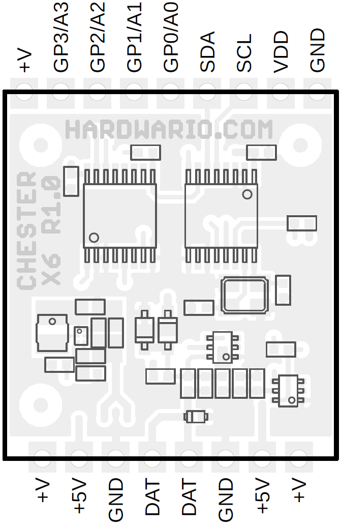
The module uses a standardized header layout compatible with CHESTER extension slots.
The pin configuration shown is for the CHESTER-M CGLS mainboard.
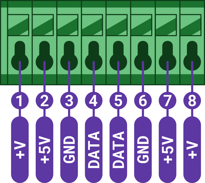
CHESTER-X6 Connector Pinout
| Pin | Signal | Type | Description |
|---|---|---|---|
| 1 | +V | Power | System positive rail (depends on the CHESTER power-supply option) |
| 2 | +5V | Power Output | Regulated 5.0 V peripheral supply (from the on-board boost) |
| 3 | GND | Ground | System ground reference |
| 4 | DATA | S-Wire | S-Wire data line |
| 5 | DATA | S-Wire | S-Wire data line (same net as pin 4) |
| 6 | GND | Ground | System ground reference |
| 7 | +5V | Power Output | Regulated 5.0 V peripheral supply (same net as pin 2) |
| 8 | +V | Power | System positive rail (same net as pin 1) |
The terminal block brings the single S-Wire bus out on a mirrored 8-pin layout: pins 4 and 5 are the same DATA net, pins 2 and 7 the same +5 V, pins 1 and 8 the same +V, and pins 3 and 6 GND. This lets peripherals be wired from either side or daisy-chained. +5V is the regulated peripheral supply from the on-board boost (switchable over I²C); +V is the system positive rail and its voltage depends on the CHESTER power-supply option.
Host Interface (I²C)
CHESTER-X6 is controlled entirely over the standard I²C bus; it has two I²C devices:
| Device | I²C address | Function |
|---|---|---|
| SC16IS740IPW | 0x4D | I²C-to-UART bridge. The S-Wire UART engine (TX/RX to the line driver) |
| TCA9534APW | 0x39 | GPIO expander. Enables the 5 V boost, resets the bridge, and handles the bridge interrupt |
All S-Wire traffic is carried over the UART bridge, and peripheral power, reset, and interrupt handling go through the expander, so the module needs only the I²C bus (SDA/SCL) and power from the slot. The slot's GP pins are not used.
S-Wire Connection
Wire each S-Wire peripheral to the terminal block: DATA (pin 4 or 5), +5V (pin 2 or 7) for power, and GND (pin 3 or 6). Because the DATA, +5 V, +V, and GND pins are mirrored across the block, peripherals can be daisy-chained: wire one peripheral to pins 1–4 and another to pins 5–8, or loop the bus through.
All peripherals must share a common GND with the module. Enable the 5 V supply over I²C (via the expander) before communicating with the peripherals.
Enclosure Feed-Through
Two options bring the S-Wire cable into the enclosure:
- Cable gland (default): route the conductors through a cable gland in the enclosure wall and wire them to the terminal block.
- Panel-mount connector (on request): an external connector in the enclosure wall lets the user plug in the cable, with no loose wiring inside. Available on request.
Compatible CHESTER Configurations
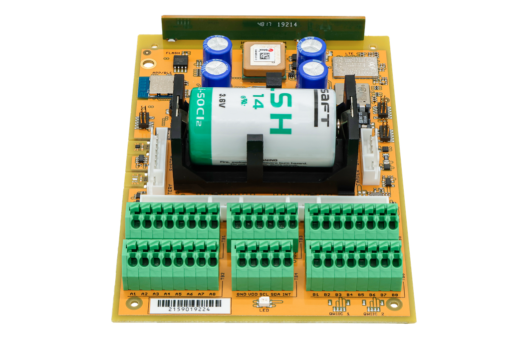
The CHESTER-X6 module can be used with various CHESTER mainboard configurations. Below are examples of compatible setups:
CHESTER-M (CGLS)
CHESTER-C4
Schematic Diagrams
The complete schematic (the SC16IS740 UART bridge, the TCA9534A expander, the S-Wire line driver, and the 5 V boost converter) is available as a PDF:
Module Drawing