CHESTER-X3
This article describes the CHESTER-X3A, CHESTER-X3B and CHESTER-X3C extension modules.
CHESTER-X3A Module Overview
CHESTER-X3A provides 2 inputs for RTD (resistive temperature devices) sensors, such as Pt 100 and Pt 1000. Each input supports 4 wire sensor connection to improve the accuracy.
CHESTER-X3B Module Overview
CHESTER-X3B allows connecting 2 type-K thermocouples (types B/C/E/J/N/R/S/T support on request) using 2 wire sensor connection.
First sensor connects to CH1A(-) and CH1B(+). If X3B is in the slot A, then you have to use terminals A2(-) and A3(+).
The second sensor connects to CH2A(-) and CH2B(+). If X3B is in the slot A, then you have to use terminals A6(-) and A7(+).
CHESTER-X3C Module Overview
CHESTER-X3C provides 2 inputs for load-cell (strain gauge) that can be used for weight measurements. Each channel use 4 wire connection.
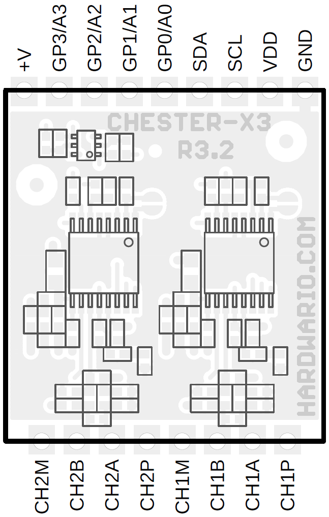
CHESTER Pin Configuration Diagram
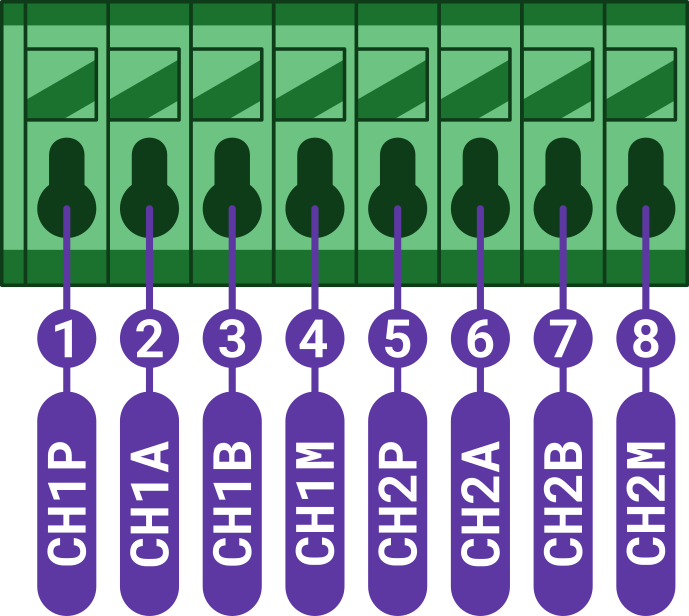
Pin Configuration and Functions
| Position | Signal Name | Signal Description |
|---|---|---|
| 1 | CH1P | Channel 1: sensor positive supply |
| 2 | CH1A | Channel 1: sensor input A |
| 3 | CH1B | Channel 1: sensor input B |
| 4 | CH1M | Channel 1: sensor negative supply |
| 5 | CH2P | Channel 2: sensor positive supply |
| 6 | CH2A | Channel 2: sensor input A |
| 7 | CH2B | Channel 2: sensor input B |
| 8 | CH2M | Channel 2: sensor negative supply |
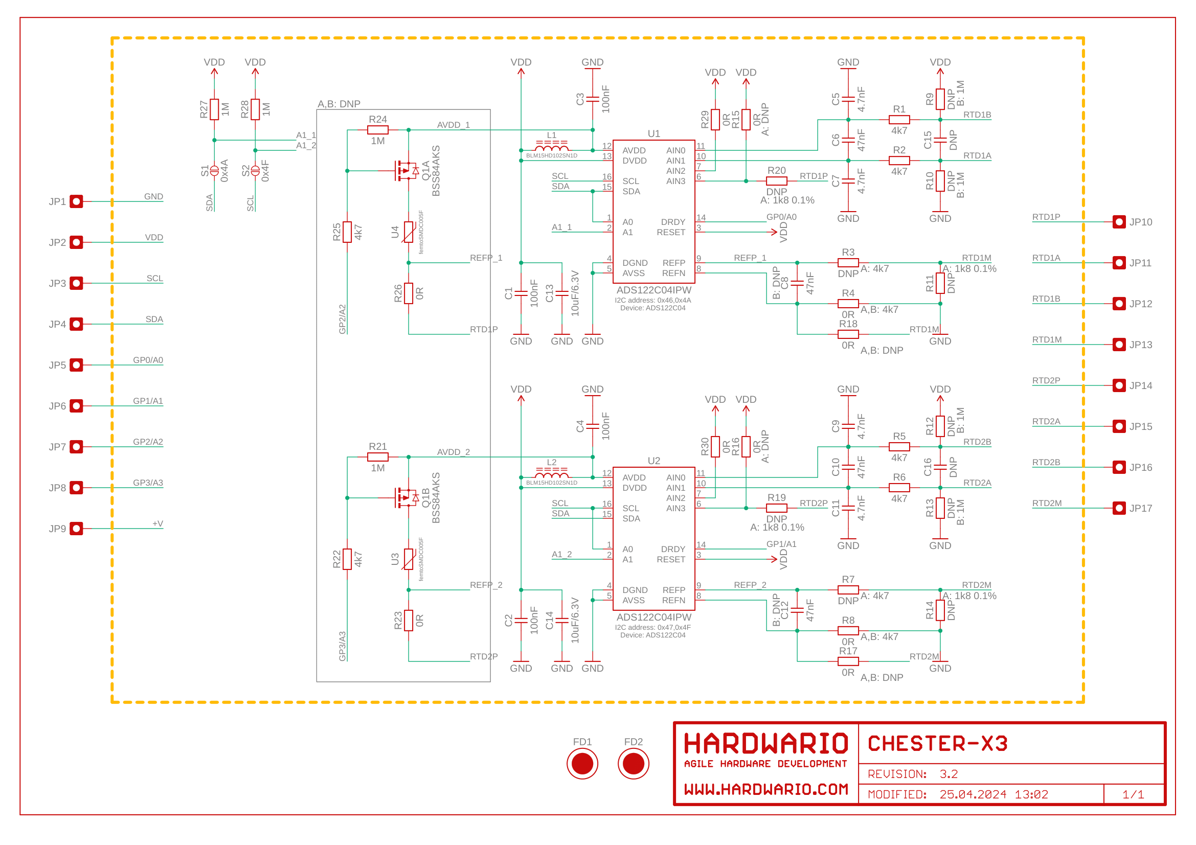
Schematic diagram
A schematic diagram is useful if you program low-level hardware-related code or if you're just curious about how the system is designed.
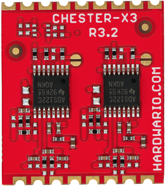
Module Drawing