Antenna Gain & Output Power
This page explains how transmit (TX) power works on a MikroTik LoRa gateway
(R11e-LR8G / wAP LR8G kit) and how to configure the antenna-gain setting so the
gateway stays within the legal radiated-power limit (EIRP).
There is no "TX power" setting on the gateway. The card's only RF control is
antenna-gain, and its factory default is 0. If you attach an antenna with gain
and leave the default, the gateway will radiate above the intended power and can
exceed the legal EIRP limit.
What is antenna gain?
Antenna gain describes how much an antenna concentrates radio energy in certain directions, compared to a theoretical antenna that radiates equally in every direction (an isotropic radiator). It's expressed in dBi — decibels relative to isotropic.
A higher-gain antenna doesn't transmit more energy — it takes the same total power and squeezes it into a narrower radiation pattern, concentrating more of it toward the horizon and less straight up/down. Total radiated power stays the same; gain only redistributes it.
Range vs. coverage radius
Two things are easy to confuse:
- Range — how far the signal reaches in the antenna's strongest direction (for an omnidirectional antenna, that's toward the horizon).
- Coverage radius — how much of the surrounding space, in every direction (including straight down, straight up, nearby floors of a building), actually gets usable signal.
A higher-gain omnidirectional antenna increases horizontal range by narrowing the vertical beamwidth. That's good for long links over flat, open terrain — but it can leave a coverage gap directly under or very close to the gateway, since less energy goes that way. A device right below a high-mounted, high-gain antenna can have worse signal than one much farther away on the horizon.
| Antenna gain | Vertical beamwidth | Best for |
|---|---|---|
| Low (~0–2 dBi) | Wide | Devices close by / at many different heights — e.g. indoors, multi-floor buildings |
| Higher (~6+ dBi) | Narrower | Long-range outdoor links, devices roughly level with or below the gateway, spread horizontally |
Match the antenna's gain to the deployment, not just to "more range = better."
How TX power actually works
A MikroTik LoRa gateway does not set its own transmit power. The value comes from the LoRaWAN Network Server and the gateway only compensates for the antenna:
radio output (at the connector) = server_value − antenna-gain
radiated EIRP                    = radio output + antenna gain − cable loss
server_value— the TX power the Network Server requests, in dBm EIRP (Semtech UDPtxpk.powefield). In ChirpStack this isdownlink_tx_powerin the region file (e.g.region_eu868.toml);-1means "use the band maximum".antenna-gain— a MikroTik gateway setting, in dBi. It is a subtraction, not a boost. It exists so that after the antenna adds its gain back, the radiated EIRP matches what the server asked for.
A higher antenna-gain value produces lower power out of the radio. It is a
compensation knob for regulatory compliance, not a way to increase range.
Configure antenna-gain
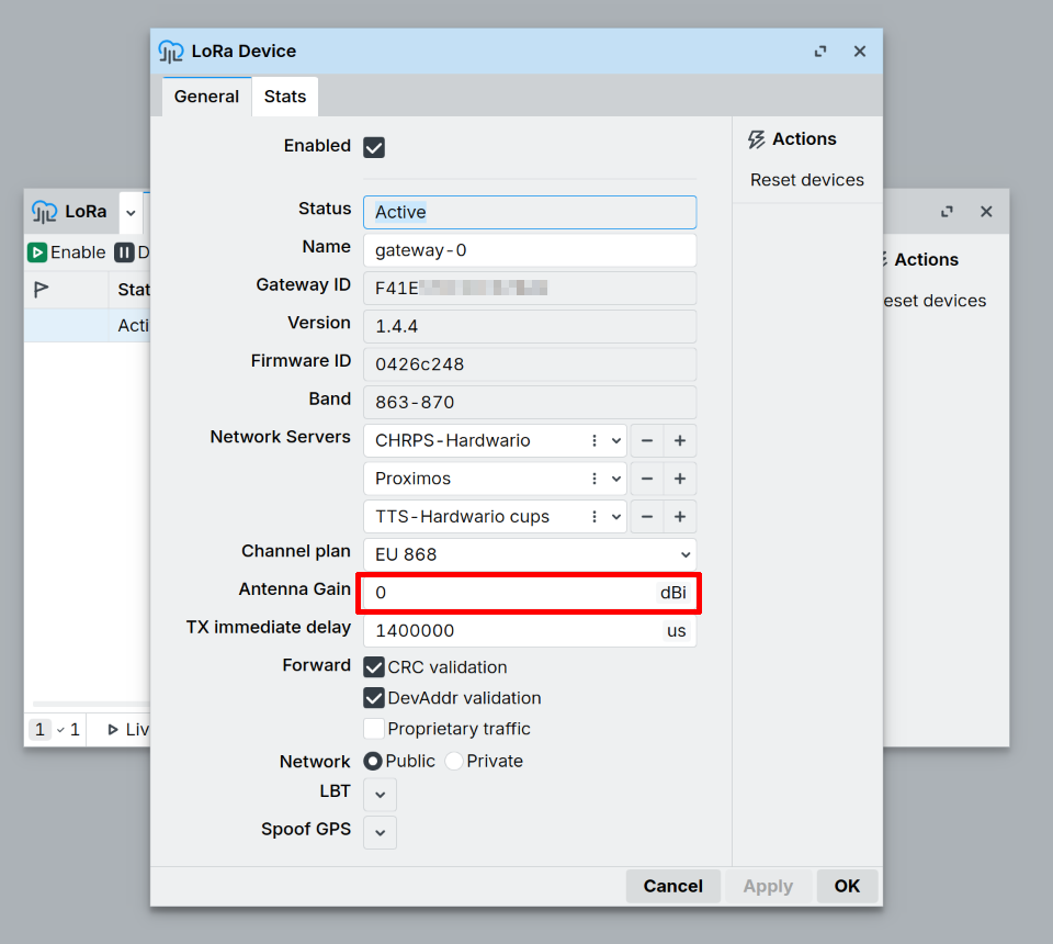
Enter the real gain of the attached antenna in dBi, minus cable loss.
For the full list of LoRa parameters and their exact definitions, see the MikroTik documentation: LoRa General Properties.
WebFig / WinBox
- Open LoRa in the left menu.
- Click the LoRa interface (e.g.
lora1). - Go to the General tab.
- Set Antenna Gain to the antenna's gain in dBi.
- Click Apply.
CLI (terminal / SSH)
/lora print
/lora set [find] antenna-gain=2
On newer RouterOS builds the menu may be /iot lora instead of /lora. If /lora is not found, use
/iot lora set [find] antenna-gain=2.
Recommended values
| Antenna | Gain | antenna-gain value |
|---|---|---|
| wAP LR8G kit built-in antenna (868 MHz) | 2 dBi | 2 |
MikroTik omni LoRa antenna kit (TOF-0809-...) | 6.5 dBi | 6.5 |
| Other external antenna | see its datasheet | antenna dBi − cable loss |
On EMBER the value has to match whichever antenna is actually connected to the LoRa card — the internal LoRaWAN antenna it ships with, or an external antenna on the LRW connector (its gain minus the loss of the cable between them). Update the setting whenever you switch between the two.
If the antenna gain is unknown, err on the higher side — the gateway will back off its power further and stay within legal limits.
Worked example (EU868)
Downlink on 869.525 MHz, EIRP limit 27 dBm, 6.5 dBi antenna, server requests
powe = 27:
antenna-gain | Radio output | Radiated EIRP | Result |
|---|---|---|---|
0 (default) | 27 dBm | 33.5 dBm | ✗ 6.5 dB over the limit |
6.5 | 20.5 dBm | 27 dBm | ✓ correct |
4.5 (6.5 dBi antenna − 2 dB cable) | 22.5 dBm | 27 dBm | ✓ correct |
Changing the transmit power itself
Because the gateway takes its power from the Network Server, change the downlink TX
power there — for example in ChirpStack, downlink_tx_power (dBm EIRP) in
region_eu868.toml. The uplink TX power is a property of the end device (node
firmware or ADR from the server), not the gateway.
To increase real-world range, use a better antenna and/or shorter, lower-loss cable —
then update antenna-gain accordingly. The setting itself never adds power.
On MikroTik's standalone wAP LR8G kit, the internal antenna is not connected from the factory. Attach it to the card's RFIO u.FL connector (with the device powered off) before use, or the card cannot transmit or receive over the antenna at all.
Regulatory limits (EU868)
- Uplink: max 25 mW = 14 dBm
- Downlink on 869.525 MHz (RX2 band): up to 500 mW = 27 dBm EIRP
- EIRP = TX power (dBm) + antenna gain (dBi) − cable loss (dB)
Always check the LoRaWAN Regional Parameters and your local regulations for the values that apply to your deployment.
Further reading
- MikroTik — LoRa General Properties
— full reference for all LoRa configuration parameters, including
antenna-gain.