Schneider Electric IEM3XXX Series
Description
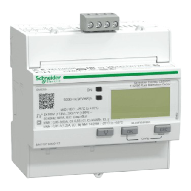
The iEM3200 series consists of compact, DIN-rail mounted energy meters designed for accurate and certified measurement of electrical energy in single-phase and three-phase systems. These meters are MID-compliant, making them suitable for both fiscal metering and cost allocation applications in residential, commercial, and light industrial installations.
This energy meter requires the use of an external sensor, such as a current transformer (CT), to measure current. The sensor must be selected based on the expected load and system configuration.
Power Installation�
Example of Installation: Schneider Electric Energy Analyzer IEM3250
| Schneider Electric Energy Analyzer IEM3250 | |
|---|---|
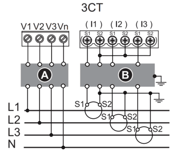
| Pin V1 | L1 |
| Pin V2 | L2 |
| Pin V3 | L3 |
| Pin Vn | N |
In this case, it is also possible to connect the energy analyzer in single-phase mode, by wiring the neutral (N) to the Vn terminal and the phase (L) to terminal V1.
Sensor Installation
Example of Installation: Carlo Gavazzi AC Current Transformer CTD-1X 100 5A XXX
| Electric Energy Analyzer IEM3250 | Carlo Gavazzi AC Current Transformer CTD-1X 100 5A XXX |
|---|---|
| Pin S1 | S1 (K) |
| Pin S2 | S2 (L) |
Connection Diagram (IEM3250)
Modbus Communication
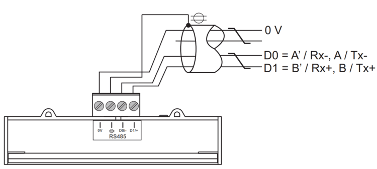
Example of Modbus Communication Installation: Schneider Electric Energy Analyzer IEM3250
| Schneider Electric Energy Analyzer IEM3250 | CHESTER Modbus |
|---|---|
| Pin D0/- | Pin 6 (A−) |
| Pin D1/+ | Pin 7 (B+) |
| Pin 0V | Pin 1 (GND) |
Modbus communication (IEM3250)
Browsing and Configuration
-
▼Arrow button- Navigation through the menu
- Increasing/Decreasing the value
-
OKSelect / Enter / Menu button -
ESCEscape button
Modbus Communication and CT Ratio Configuration for Energy Analyzer
- Press and hold the
OKandESCbuttons until the password prompt appears. - Enter the password using the
▼(Arrow button) button. (Default password for new meters is0010.) - After entering the correct password, the configuration menu will appear.
- Use the
▼(Arrow button) button to navigate to the menu item:Communication – Change?. - Press the
OKbutton to enter communication settings. - Configure the following parameters as needed:
• Address
• Baud Rate
• Parity
• Stop Bit • Stop Bit - Continue using the
▼(Arrow button) button to scroll to the end of the menu. - At the
Exit Configoption, press theOKbutton to confirm and save the settings.
Default Modbus Communication Configuration
| Address | Baud Rate | Parity | Stop Bit |
|---|---|---|---|
| 1 | 9.6k | None | 1 |
Modbus Communication Configuration for Chester
Use the following commands to configure communication parameters via Chester terminal:
app config modbus-baud "9600"
app config modbus-addr "1"
app config modbus-parity "none"
app config modbus-stop-bits "1"
app config em-type "g4"
config save
Example of CT Ratio Selection
Carlo Gavazzi AC Current Transformer CTD-1X 100 5A XXX
| Model | CT Ratio |
|---|---|
| CTD-1X 100 5A XXX | 20 (100:5 → 20) |
The CT ratio is selected based on the maximum expected primary current. For example, if the system's maximum current is around 100 A, a 100:5 CT (20 CT) is chosen to step this down to 5 A for measurement devices.
Measured values
| Measured Value | Key / Path |
|---|---|
| Current | E_ENERGY_METER.METER_4.CURRENT.MEASUREMENTS |
| Power | E_ENERGY_METER.METER_4.POWER.MEASUREMENTS |
| Frequency | E_ENERGY_METER.METER_4.FREQUENCY.MEASUREMENTS |
| Energy In | E_ENERGY_METER.METER_4.ENERGY_IN.MEASUREMENTS |
| Energy Out | E_ENERGY_METER.METER_4.ENERGY_OUT.MEASUREMENTS |
| Voltage L1 | E_ENERGY_METER.METER_4.VOLTAGE_L1.MEASUREMENTS |
| Voltage L2 | E_ENERGY_METER.METER_4.VOLTAGE_L2.MEASUREMENTS |
| Voltage L3 | E_ENERGY_METER.METER_4.VOLTAGE_L3.MEASUREMENTS |
| Current L1 | E_ENERGY_METER.METER_4.CURRENT_L1.MEASUREMENTS |
| Current L2 | E_ENERGY_METER.METER_4.CURRENT_L2.MEASUREMENTS |
| Current L3 | E_ENERGY_METER.METER_4.CURRENT_L3.MEASUREMENTS |
| Power L1 | E_ENERGY_METER.METER_4.POWER_L1.MEASUREMENTS |
| Power L2 | E_ENERGY_METER.METER_4.POWER_L2.MEASUREMENTS |
| Power L3 | E_ENERGY_METER.METER_4.POWER_L3.MEASUREMENTS |