Carlo Gavazzi EM5XX Series
Description
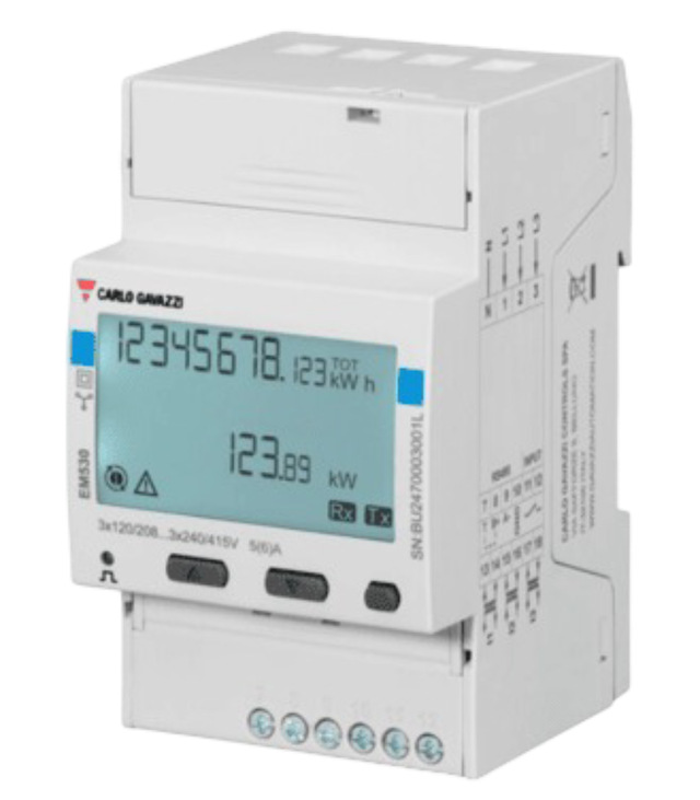
The EM5xx series offers a range of compact and versatile energy analyzers designed for monitoring electrical consumption and quality in single-phase, two-phase, and three-phase systems. These devices are ideal for use in residential, commercial, and industrial environments where accurate measurement, reliability, and ease of use are essential.
This energy meter requires the use of an external sensor, such as a current transformer (CT), to measure current. The sensor must be selected based on the expected load and system configuration.
Power Installation
Example of Installation: Carlo Gavazzi Energy Analyzer EM530
| Carlo Gavazzi Energy Analyzer - EM530 | |
|---|---|
| Pin N | N |
| Pin 1 | L1 |
| Pin 2 | L2 |
| Pin 3 | L3 |
In this case, it is also possible to connect the energy analyzer in single-phase mode, by wiring the neutral (N) to the N terminal and the phase (L) to terminal 1.
Connection Diagram (EM530)

Sensor Installation
Example of Installation: Split Core Current Transformer CTA6X200A5A
| Carlo Gavazzi Energy Analyzer - EM530 | Split Core Current Transformer - CTA6X200A5A |
|---|---|
| Pin 13 | K |
| Pin 14 | L |
Connection Diagram (CTA6X200A5A)

Modbus Communication
Example of Modbus Communication Installation: Carlo Gavazzi Energy Analyzer EM530
| Carlo Gavazzi Energy Analyzer – EM530 | CHESTER Modbus |
|---|---|
| Pin 9 | Pin 6 (A−) |
| Pin 8 | Pin 7 (B+) |
| Pin 10 | Pin 1 (GND) |
Modbus communication (EM530)

Browsing and Configuration Buttons
-
▲Up button- Navigation through the menu
- Increasing the value
-
▼Down button- Navigation through the menu
- Decreasing the value
-
⯀Select / Enter / Menu button
Modbus Communication Configuration for Energy Analyzer
- Press the Select button to open the menu.
- Use the Select button to choose the Setting option.
- Use the Up/Down buttons to select the menu item:
r5485. - Enter the configuration values according to the table below.
Default Modbus Communication Configuration
| Address | Baud Rate | Parity | Stop Bit |
|---|---|---|---|
| 1 | 9.6k | None | 1 |
Modbus Communication Configuration for Chester
Use the following commands to configure communication parameters via Chester terminal:
app config modbus-baud "9600"
app config modbus-addr "1"
app config modbus-parity "none"
app config modbus-stop-bits "1"
app config em-type "g2"
config save
CT Ratio Configuration
- Press the Select button to open the menu.
- Use the Select button to choose the Reset option.
- Use the Up/Down buttons to navigate to the menu item MID res.
- Press Start.
- Enter the CT ratio values.
- Confirm the settings by selecting YES using the Up button, then press the Select button.
These models are MID-certified meters (Measuring Instruments Directive — EU legal metrology standard).
The CT ratio can be changed only before the device registers 1 kWh of active energy.
After exceeding 1 kWh, the CT ratio becomes permanently locked and cannot be modified, even with a factory reset or MID reset.
Example of CT Ratio Selection
Carlo Gavazzi Split Core Current Transformer - CTA6X200A5A
| Model | CT Ratio |
|---|---|
| CTA6X200A5A | 40 (200:5 → 40) |
The CT ratio is selected based on the maximum expected primary current. For example, if the system's maximum current is around 200 A, a 200:5 CT (40 CT) is chosen to step this down to 5 A for measurement devices.
Measured values
| Measured Value | Key / Path |
|---|---|
| Current | E_ENERGY_METER.METER_2.CURRENT.MEASUREMENTS |
| Voltage | E_ENERGY_METER.METER_2.VOLTAGE.MEASUREMENTS |
| Power | E_ENERGY_METER.METER_2.POWER.MEASUREMENTS |
| Frequency | E_ENERGY_METER.METER_2.FREQUENCY.MEASUREMENTS |
| Energy In | E_ENERGY_METER.METER_2.ENERGY_IN.MEASUREMENTS |
| Energy Out | E_ENERGY_METER.METER_2.ENERGY_OUT.MEASUREMENTS |
| Voltage L1 | E_ENERGY_METER.METER_2.VOLTAGE_L1.MEASUREMENTS |
| Voltage L2 | E_ENERGY_METER.METER_2.VOLTAGE_L2.MEASUREMENTS |
| Voltage L3 | E_ENERGY_METER.METER_2.VOLTAGE_L3.MEASUREMENTS |
| Current L1 | E_ENERGY_METER.METER_2.CURRENT_L1.MEASUREMENTS |
| Current L2 | E_ENERGY_METER.METER_2.CURRENT_L2.MEASUREMENTS |
| Current L3 | E_ENERGY_METER.METER_2.CURRENT_L3.MEASUREMENTS |
| Power L1 | E_ENERGY_METER.METER_2.POWER_L1.MEASUREMENTS |
| Power L2 | E_ENERGY_METER.METER_2.POWER_L2.MEASUREMENTS |
| Power L3 | E_ENERGY_METER.METER_2.POWER_L3.MEASUREMENTS |