Enclosures

Standard CHESTER housing comes in two colors - light grey and dark grey. The enclosure has dimensions of 130x175x45mm and is IP67 rated.

It can be mounted using:

  • Screws through the mounting holes
  • Special zip tie holders (pole is possible)
  • Duck tape
  • Double-sided sticker (e.g., 3M Dual-Lock)
tip

You can also place the CHESTER device in an alternative enclosure. HARDWARIO produces carrier boards for larger housings - those can bring the benefit of bigger battery packs and other electrical interfaces. See the article Power Management.

List of Enclosures

Ordering CodeApplicationDrawingsDimensionsNote
CHESTER-E1-PCHESTER ClimePDF, DWG130x175x45mm
CHESTER-E2-PCHESTER CounterPDF, DWG130x175x45mm
CHESTER-E3-PCHESTER Input/CurrentPDF, DWG130x175x45mm
CHESTER-E4-FPCHESTER PushPDF, DWG130x175x45mm
CHESTER-E5-PCHESTER ScalePDF, DWG130x175x45mm
CHESTER-E6-PCHESTER Scan, Signal and TrackPDF, DWG130x175x45mm
CHESTER-E7-PCHESTER Clime IAQPDF, DWG130x175x45mmS1
CHESTER-E8-PCHESTER Input 8xPDF, DWG130x175x45mm
CHESTER-E9-PCHESTER Input 8x + DCPDF, DWG130x175x45mm
CHESTER-E10-PCHESTER MeteoPDF, DWG130x175x45mm
CHESTER-E11-PCHESTER + D1PDF, DWG130x175x45mmDisplay
CHESTER-E12-PPDF, DWG130x175x45mm
CHESTER-E13-PPDF, DWG130x175x45mm
CHESTER-E14-PPDF, DWG130x175x45mm
CHESTER-E15-PPDF, DWG130x175x45mm
CHESTER-E16-PPDF, DWG130x175x45mm
CHESTER-E17-PCHESTER with C1 (Ekoterm)PDF, DWG200x280x65mm
CHESTER-E18-PCHESTER with C2 (Axilera)PDF, DWG200x280x65mm
CHESTER-E19-PCHESTER with B1 (wM-Bus)PDF, DWG200x280x65mm

Ordering Codes

Suffix explanation:

  • -L Light color enclosure
  • -D Dark color enclosure
  • -H UV-printed HARDWARIO logo
  • -P External antenna u.FL/SMA pigtail

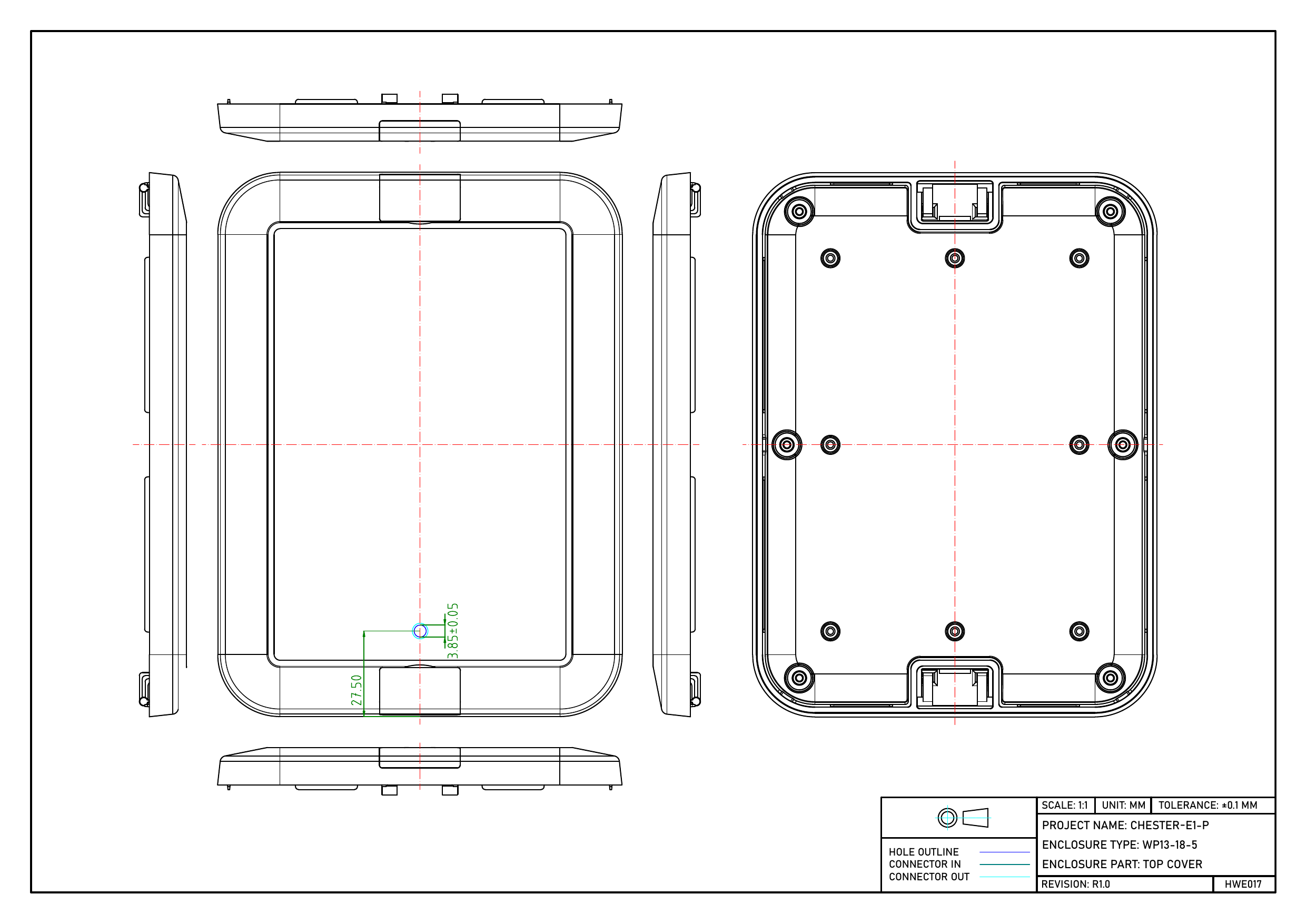
CHESTER-E1-P
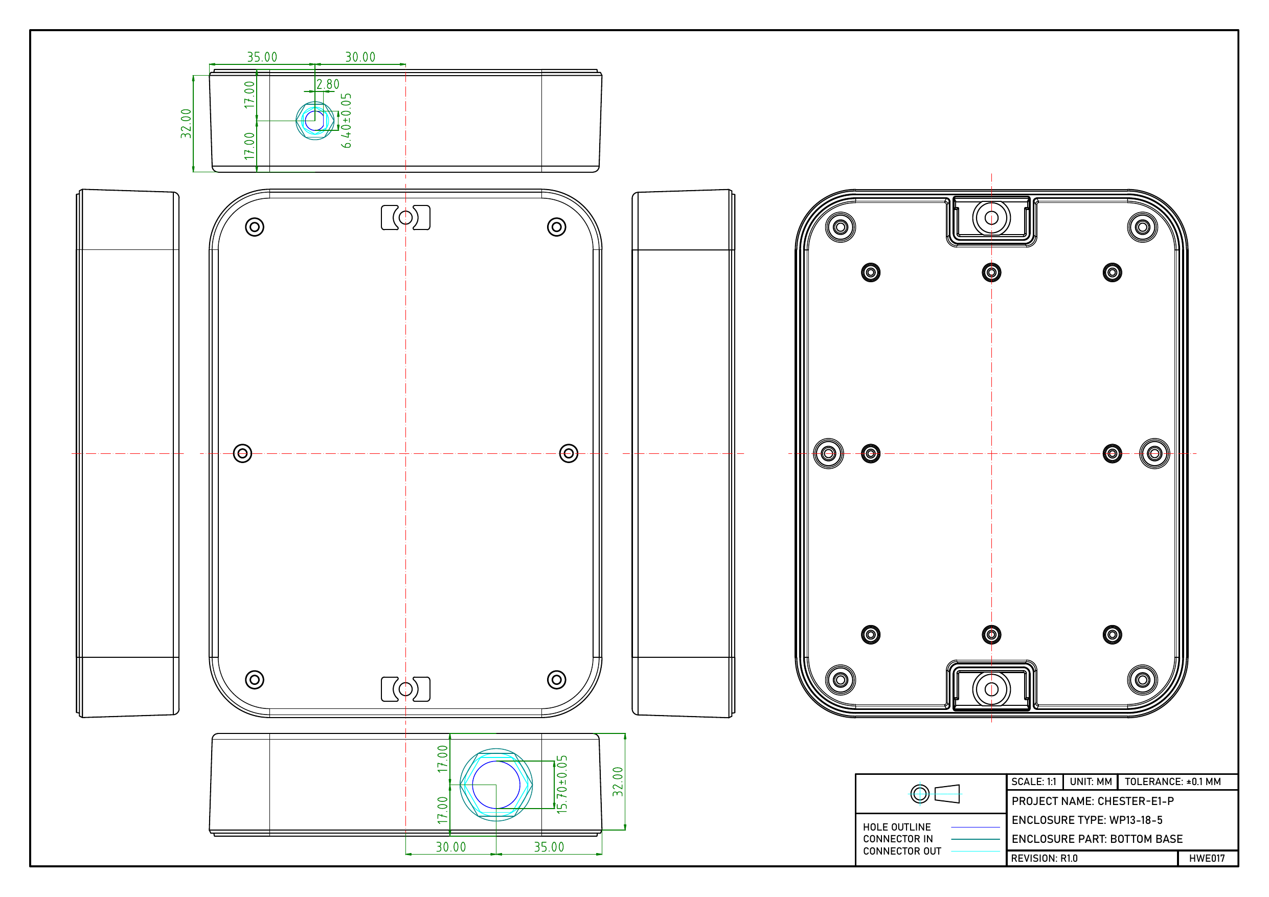
Dimensioned drawing of the CHESTER-E1-P bottom base with cable entry holes in the side walls Dimensioned drawing of the CHESTER-E1-P top cover with one small sensor hole

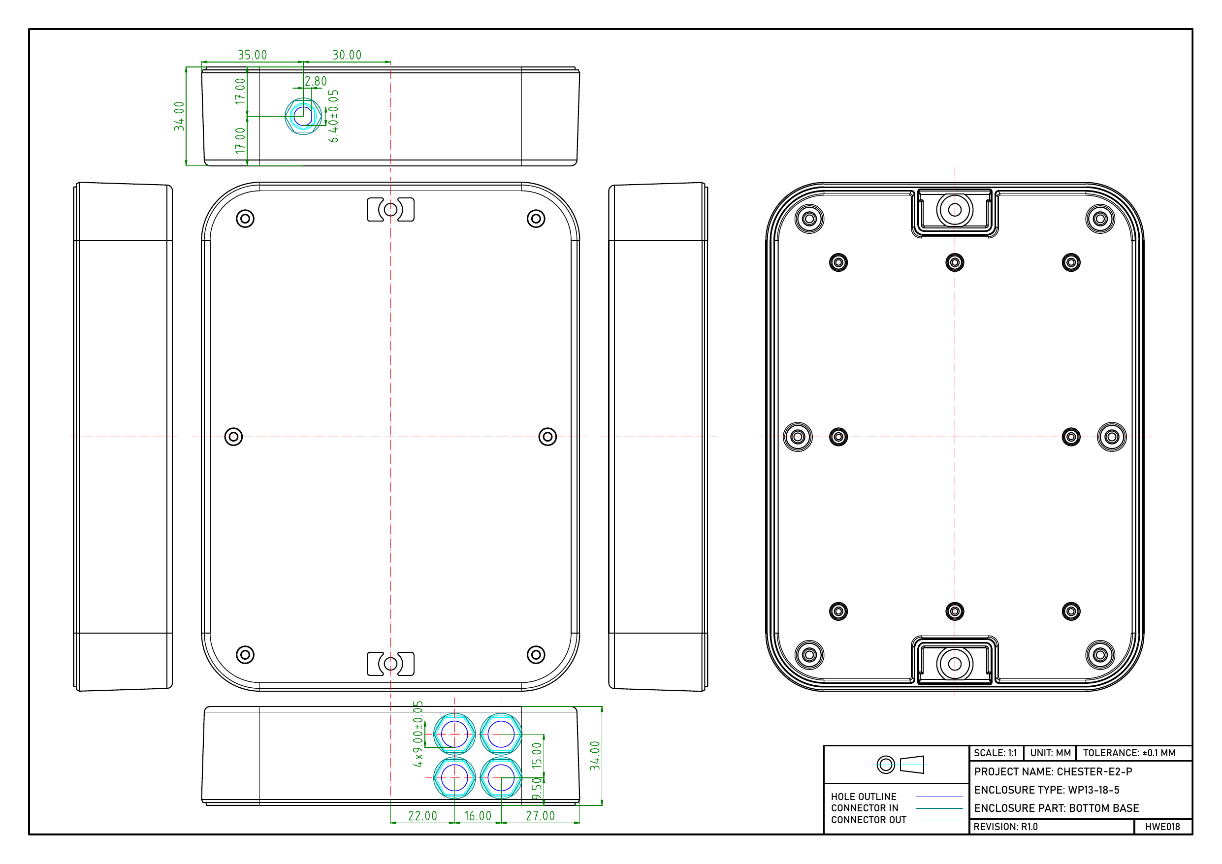
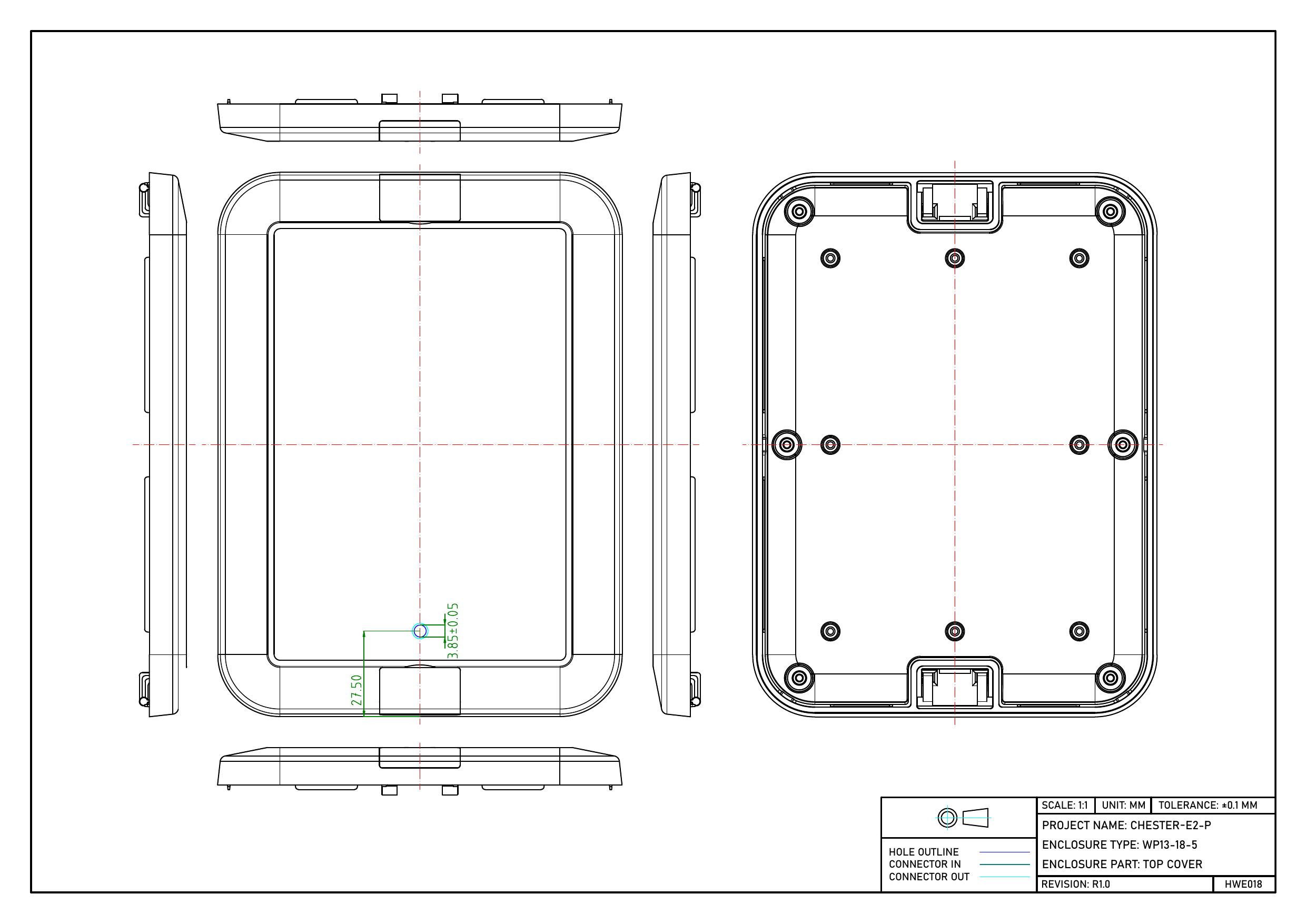
CHESTER-E2-P

Dimensioned drawing of the CHESTER-E2-P bottom base with machined hole positions Dimensioned drawing of the CHESTER-E2-P top cover with machined hole positions

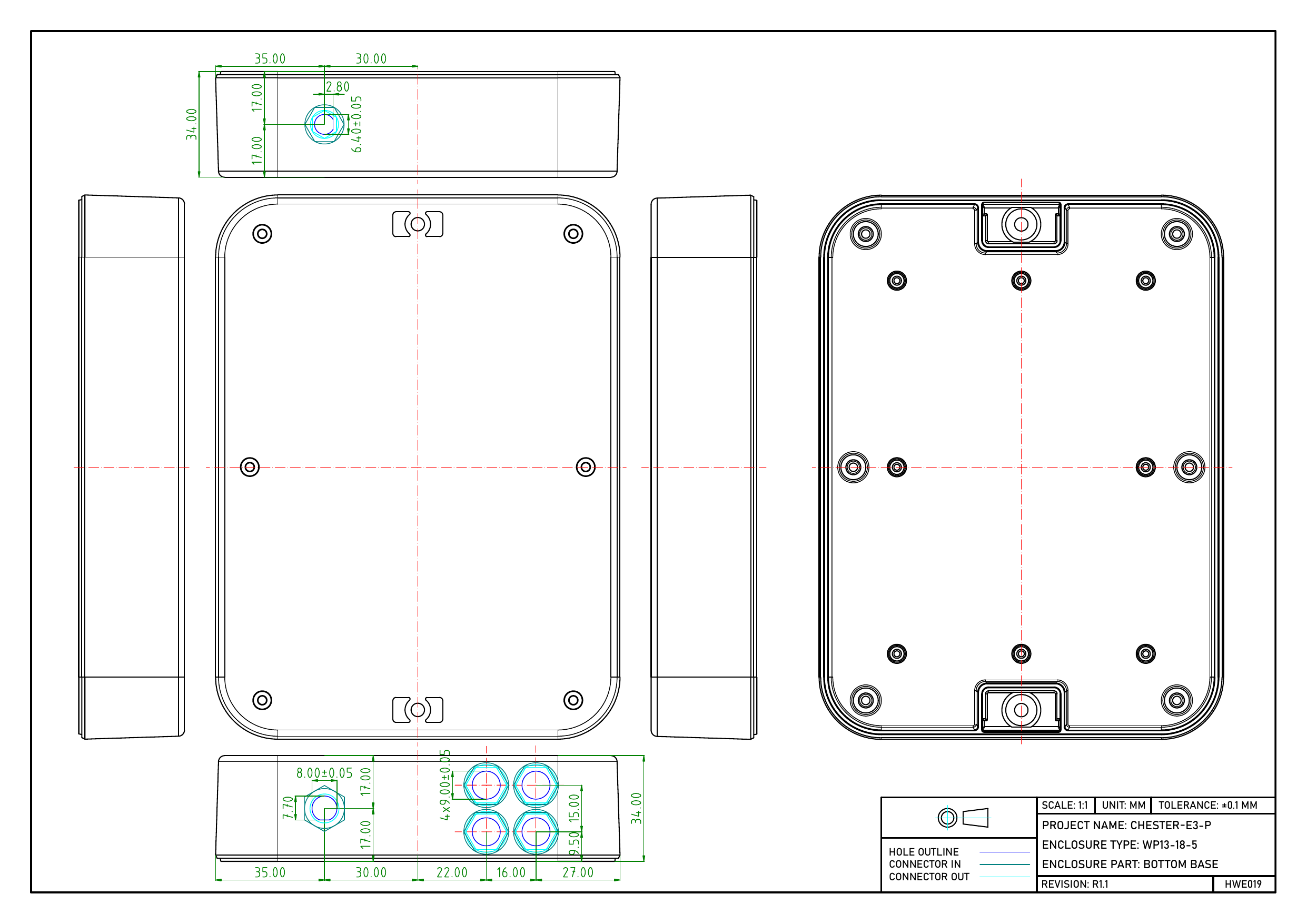
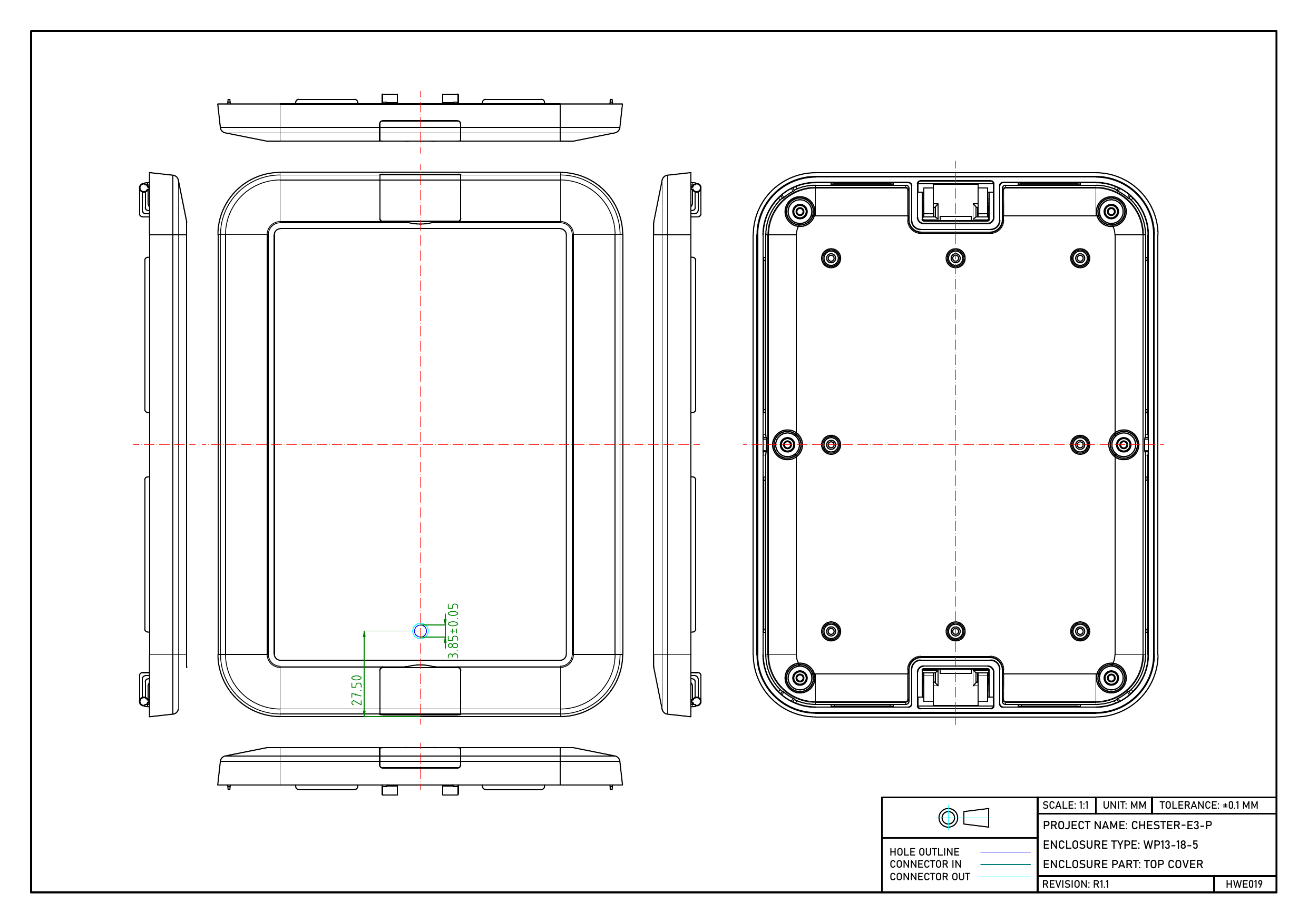
CHESTER-E3-P

Dimensioned drawing of the CHESTER-E3-P bottom base with machined hole positions Dimensioned drawing of the CHESTER-E3-P top cover with machined hole positions

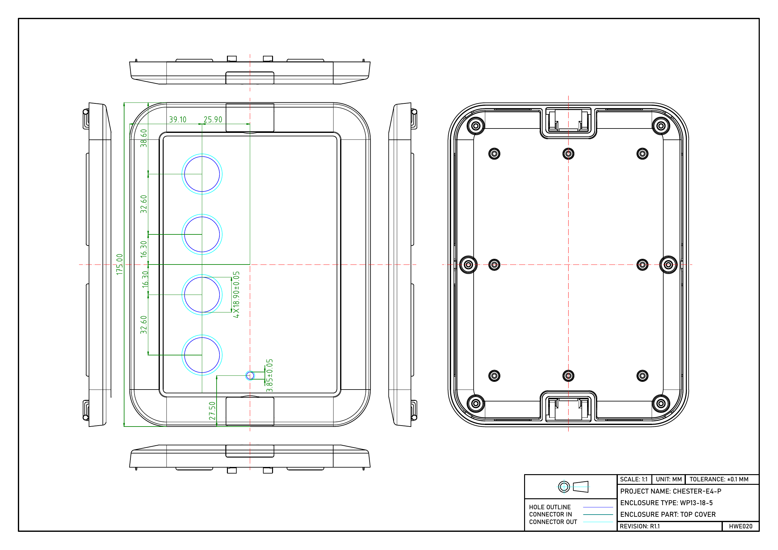
CHESTER-E4-FP

  • -F Four push buttons on the left side of the enclosure
  • -X One push button in the center of the enclosure

See 1-F or X explanation in CHESTER-Z1 Ordering Codes.
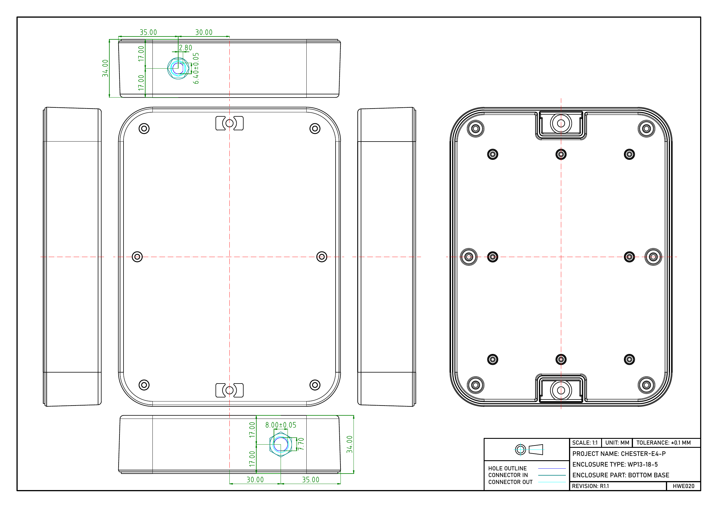
Dimensioned drawing of the CHESTER-E4-FP bottom base with machined hole positions Dimensioned drawing of the CHESTER-E4-FP top cover with four push-button holes along the left side

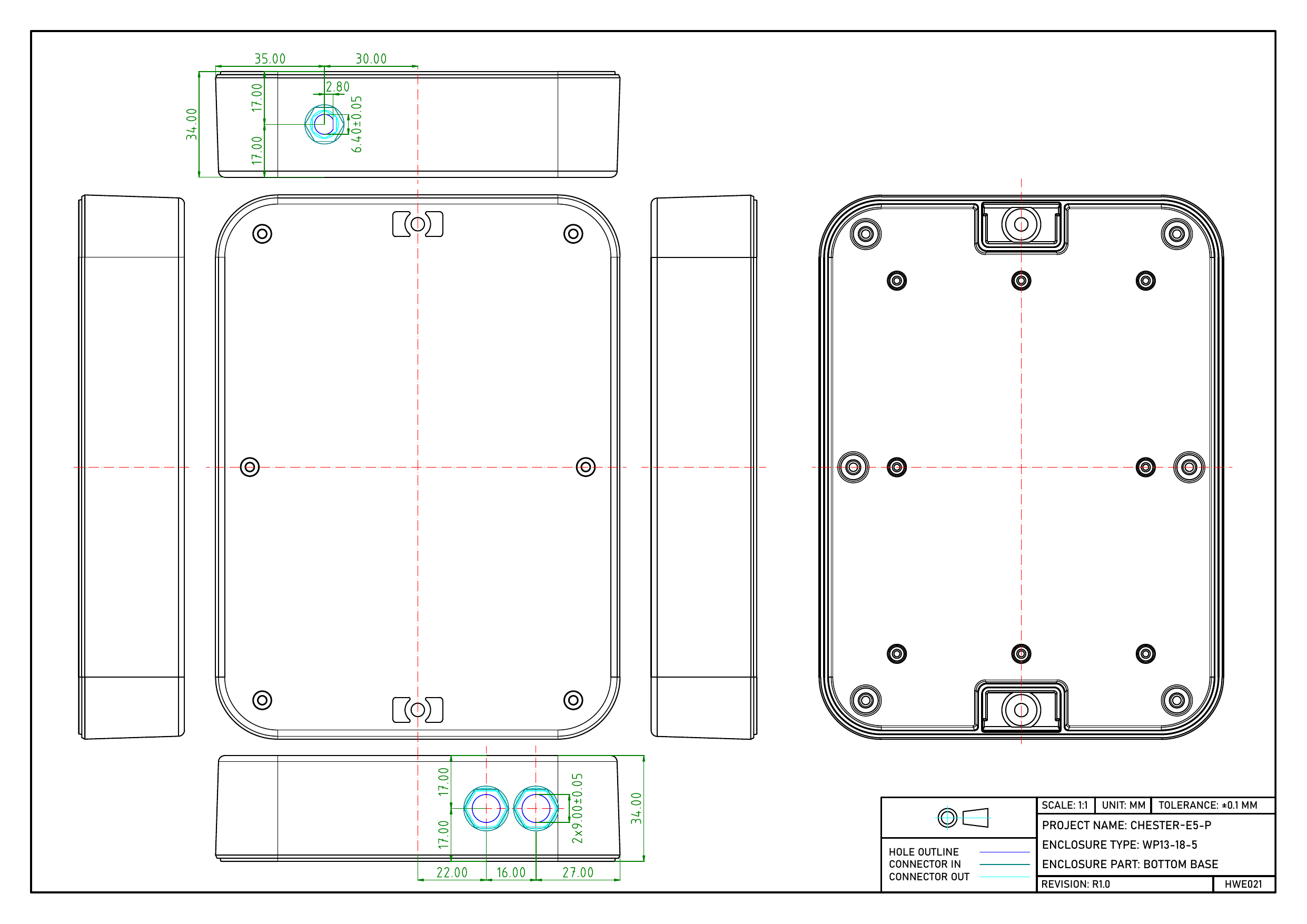
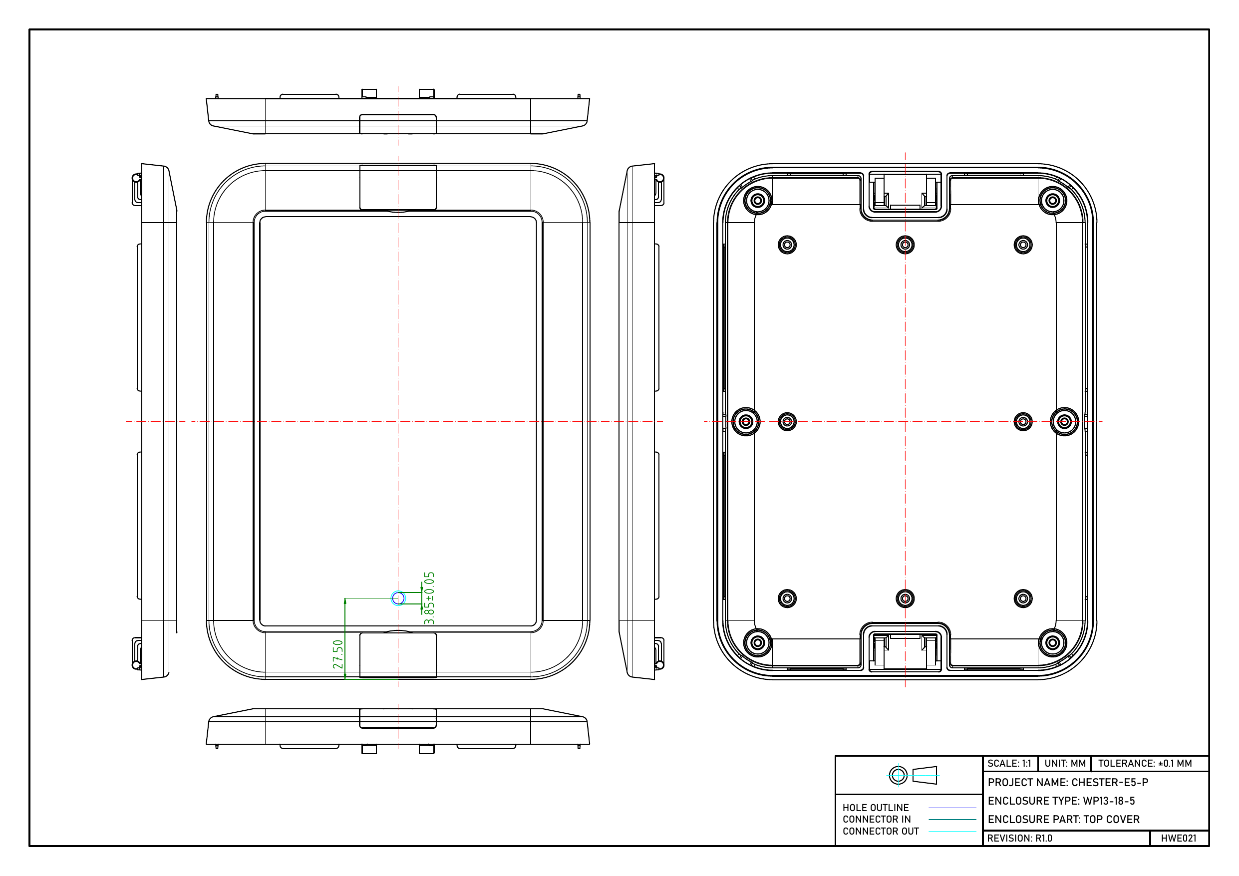
CHESTER-E5-P

Dimensioned drawing of the CHESTER-E5-P bottom base with machined hole positions Dimensioned drawing of the CHESTER-E5-P top cover with machined hole positions

CHESTER-E6-P

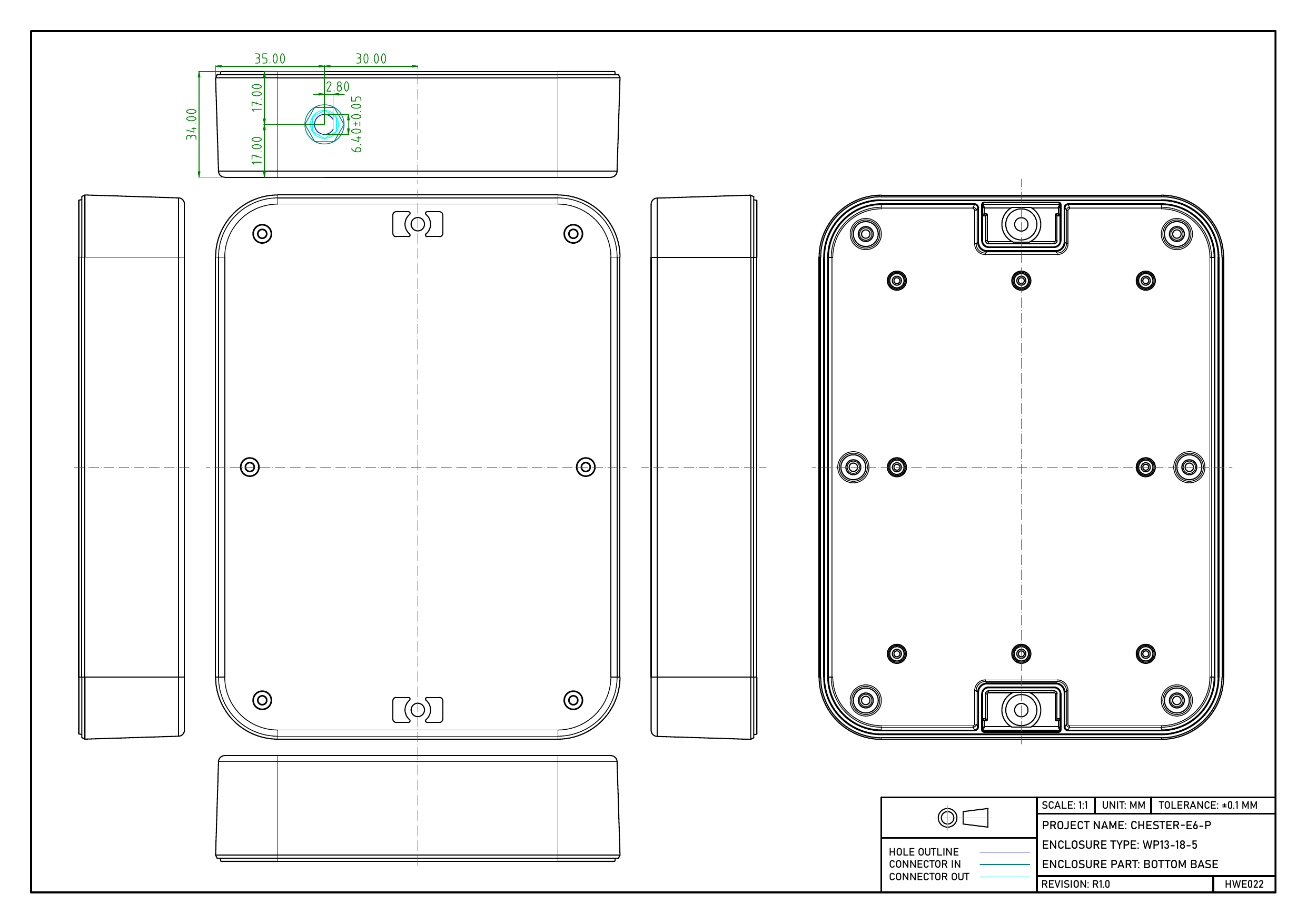
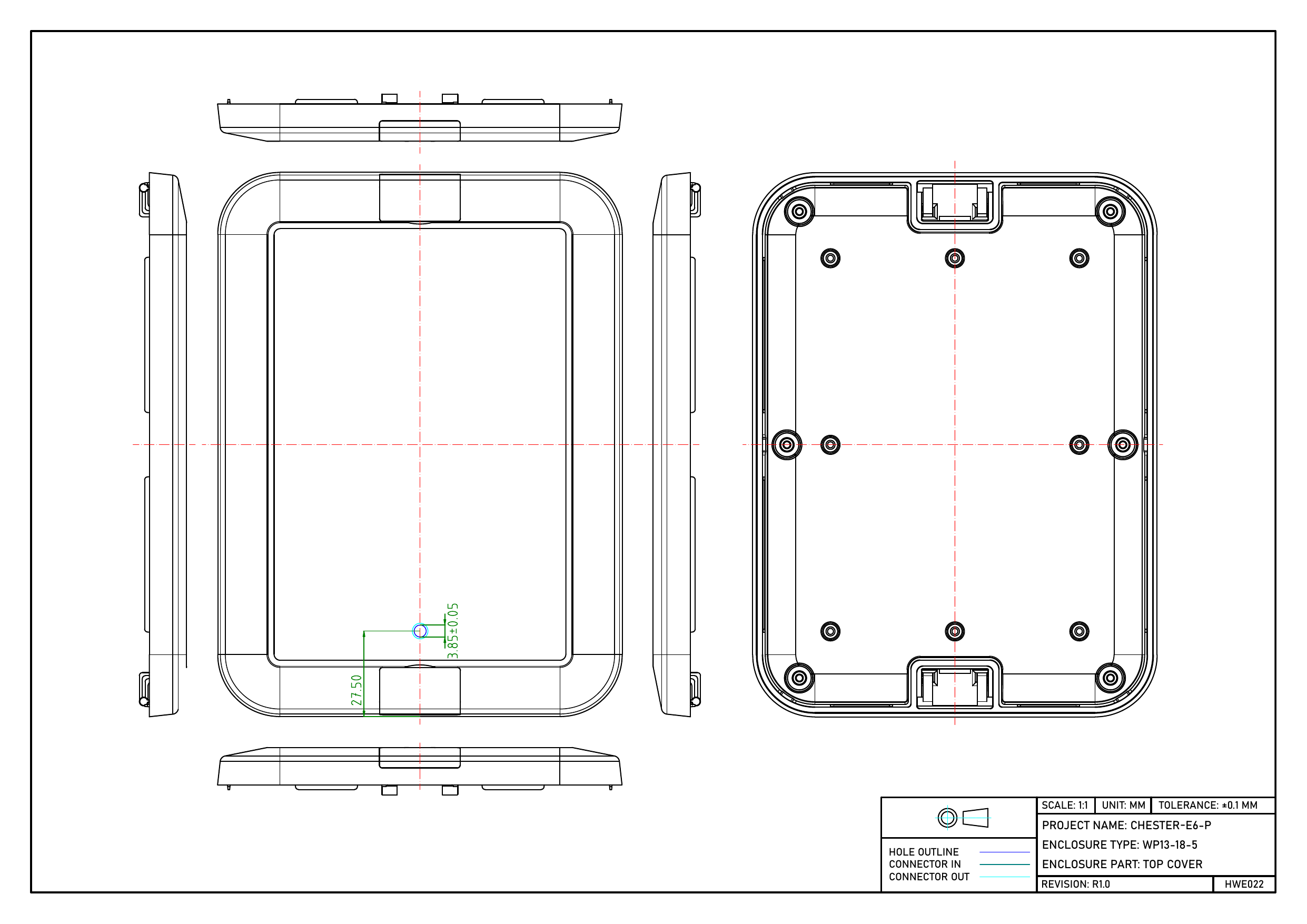
Dimensioned drawing of the CHESTER-E6-P bottom base with machined hole positions Dimensioned drawing of the CHESTER-E6-P top cover with machined hole positions

CHESTER-E7-P

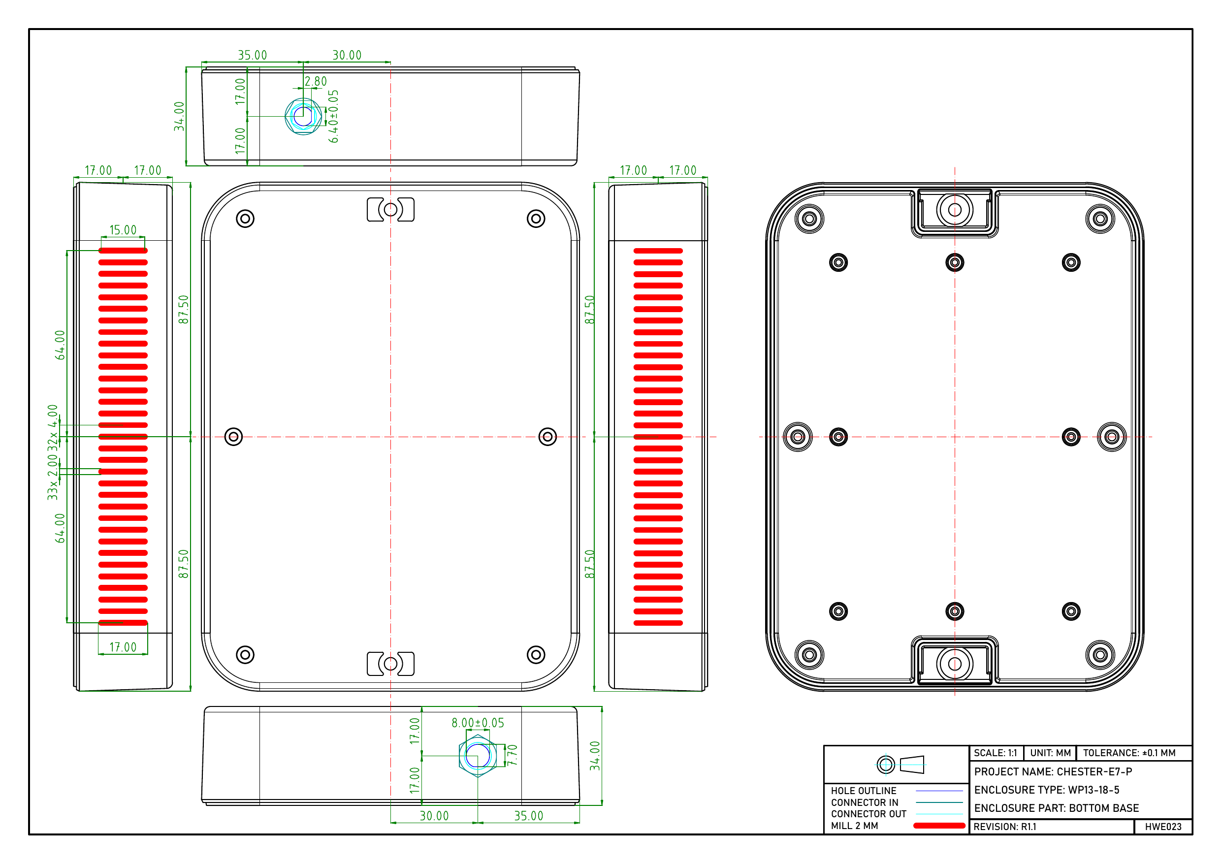
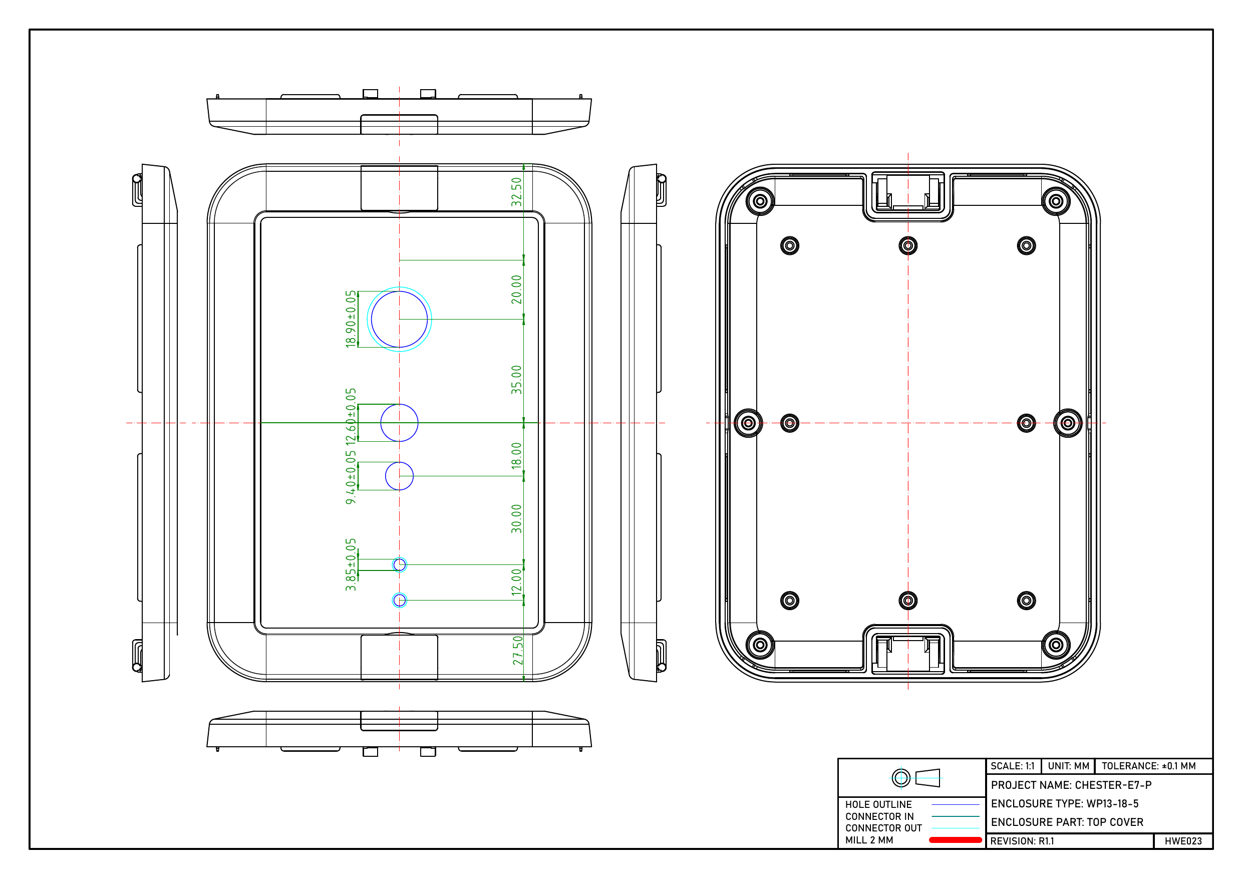
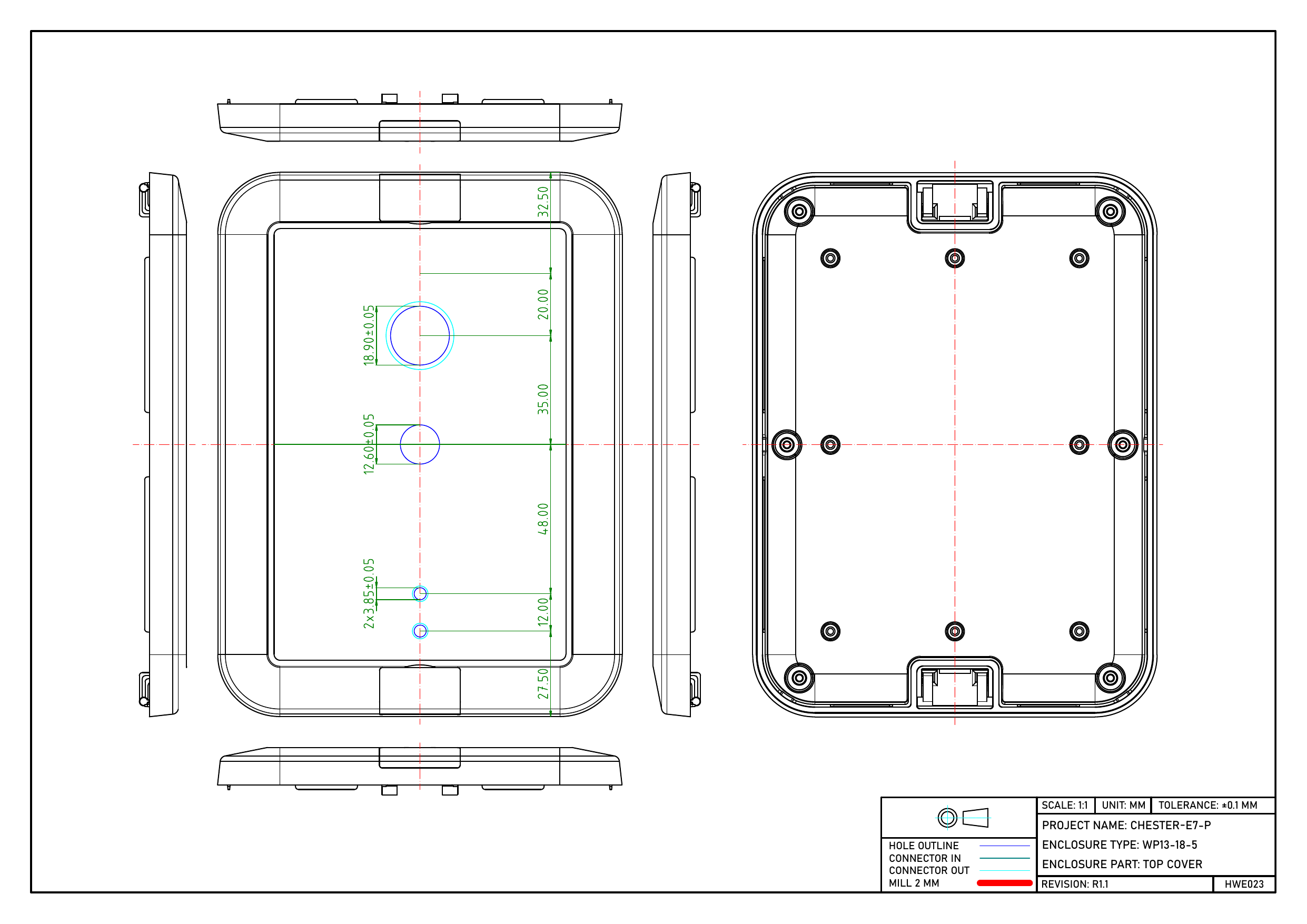
Dimensioned drawing of the CHESTER-E7-P bottom base with machined hole positions Dimensioned drawing of the CHESTER-E7-P top cover with four sensor and vent holes on the centerline Dimensioned drawing of the CHESTER-E7-P top cover variant with three sensor holes and a vent hole

CHESTER-E8-P

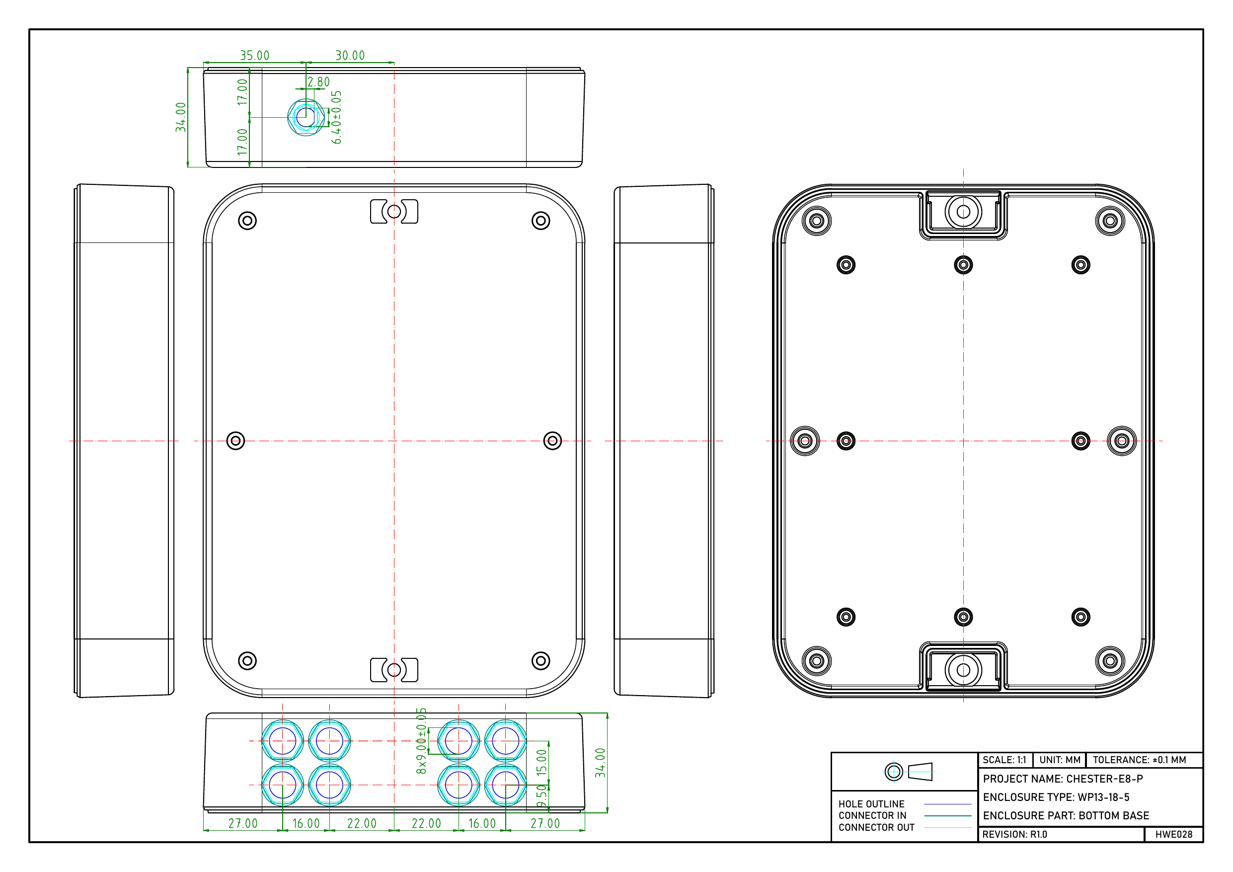
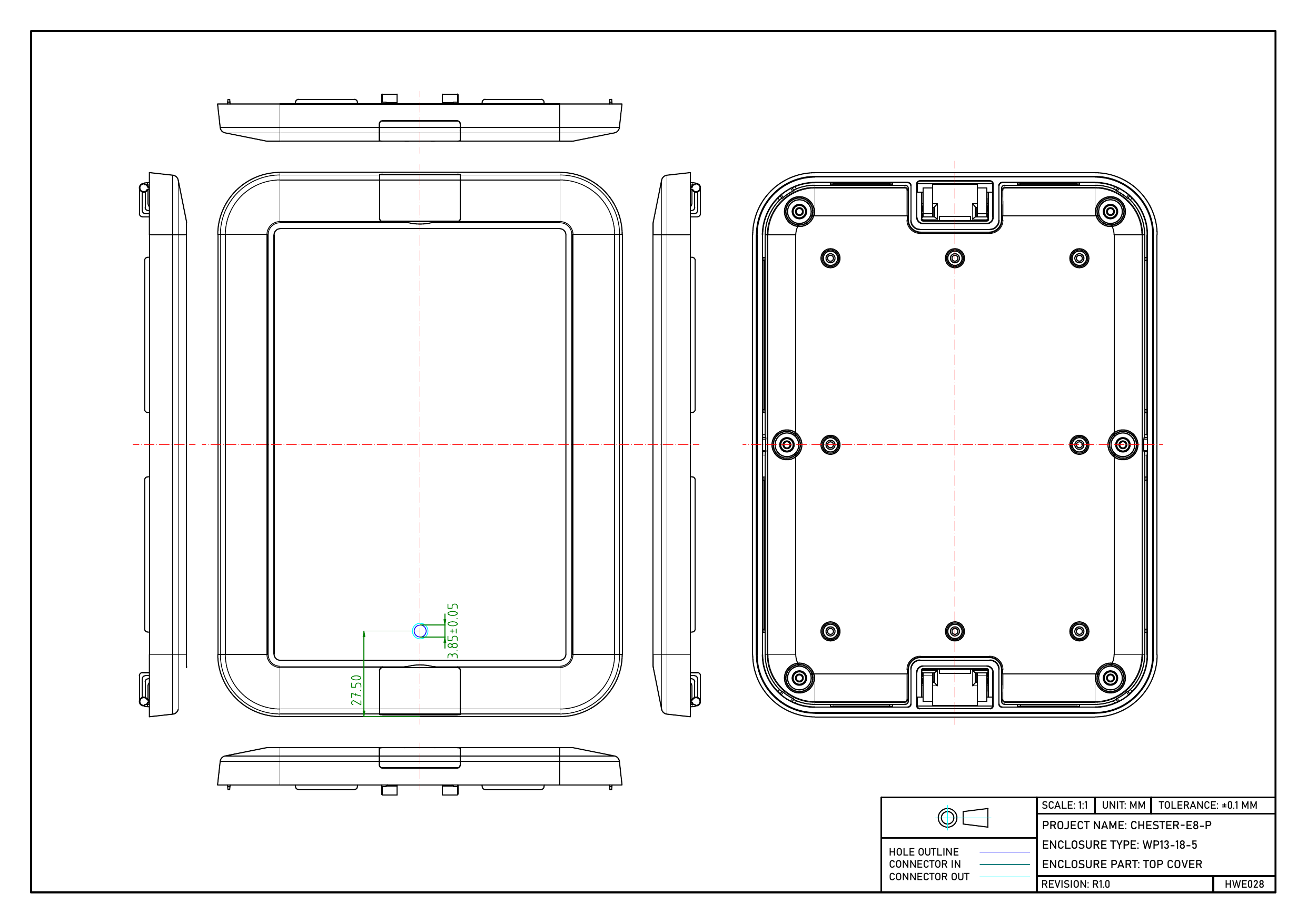
Dimensioned drawing of the CHESTER-E8-P bottom base with machined hole positions Dimensioned drawing of the CHESTER-E8-P top cover with machined hole positions

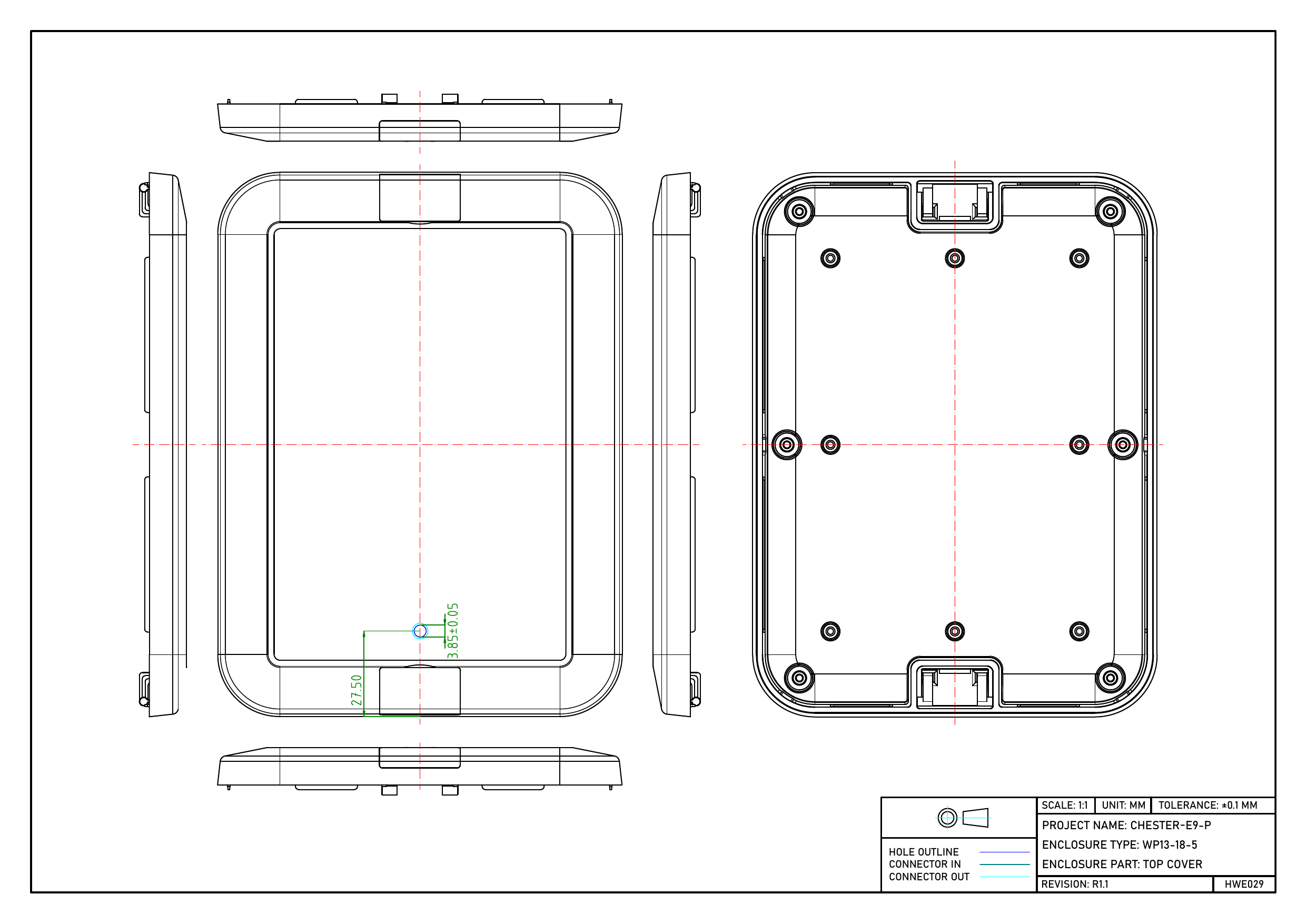
CHESTER-E9-P

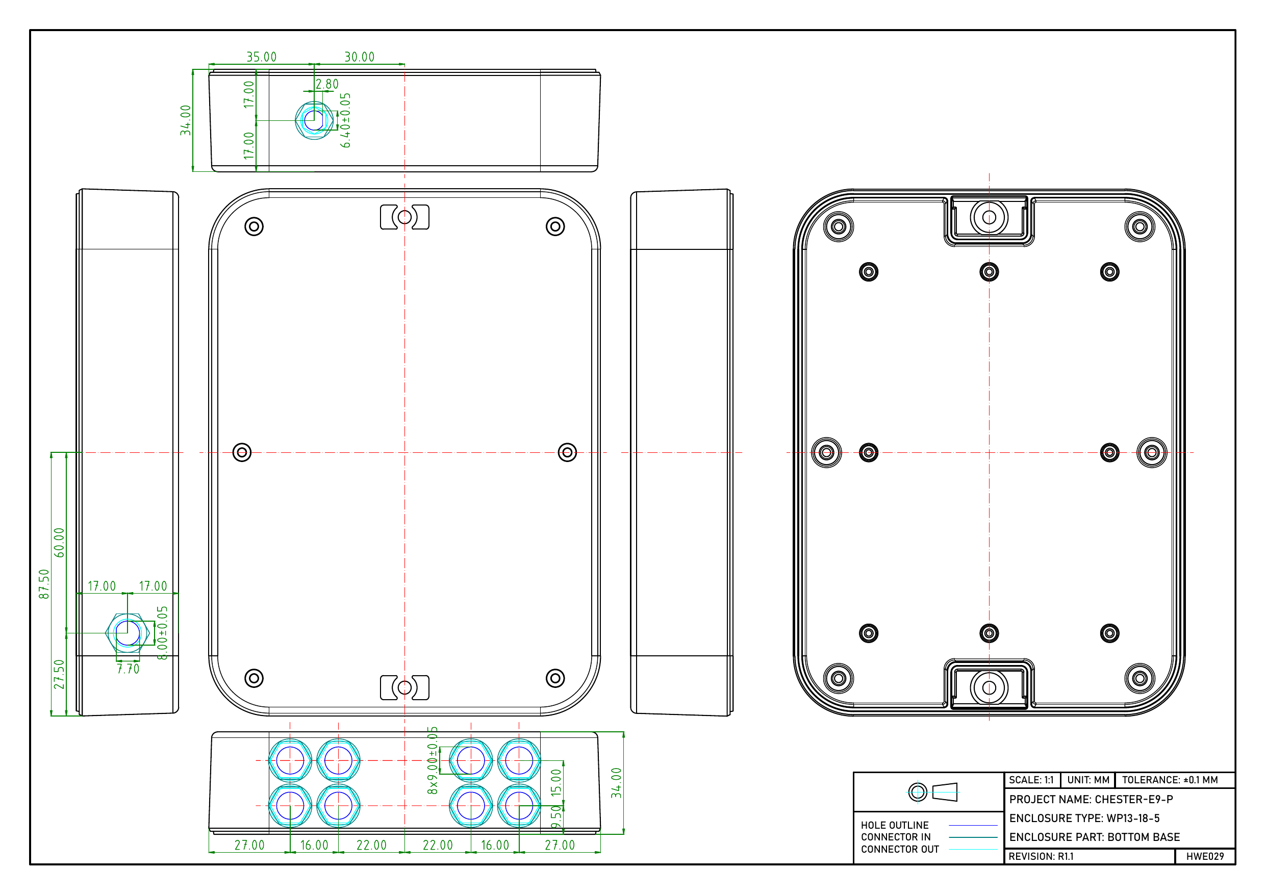
Dimensioned drawing of the CHESTER-E9-P bottom base with machined hole positions Dimensioned drawing of the CHESTER-E9-P top cover with machined hole positions

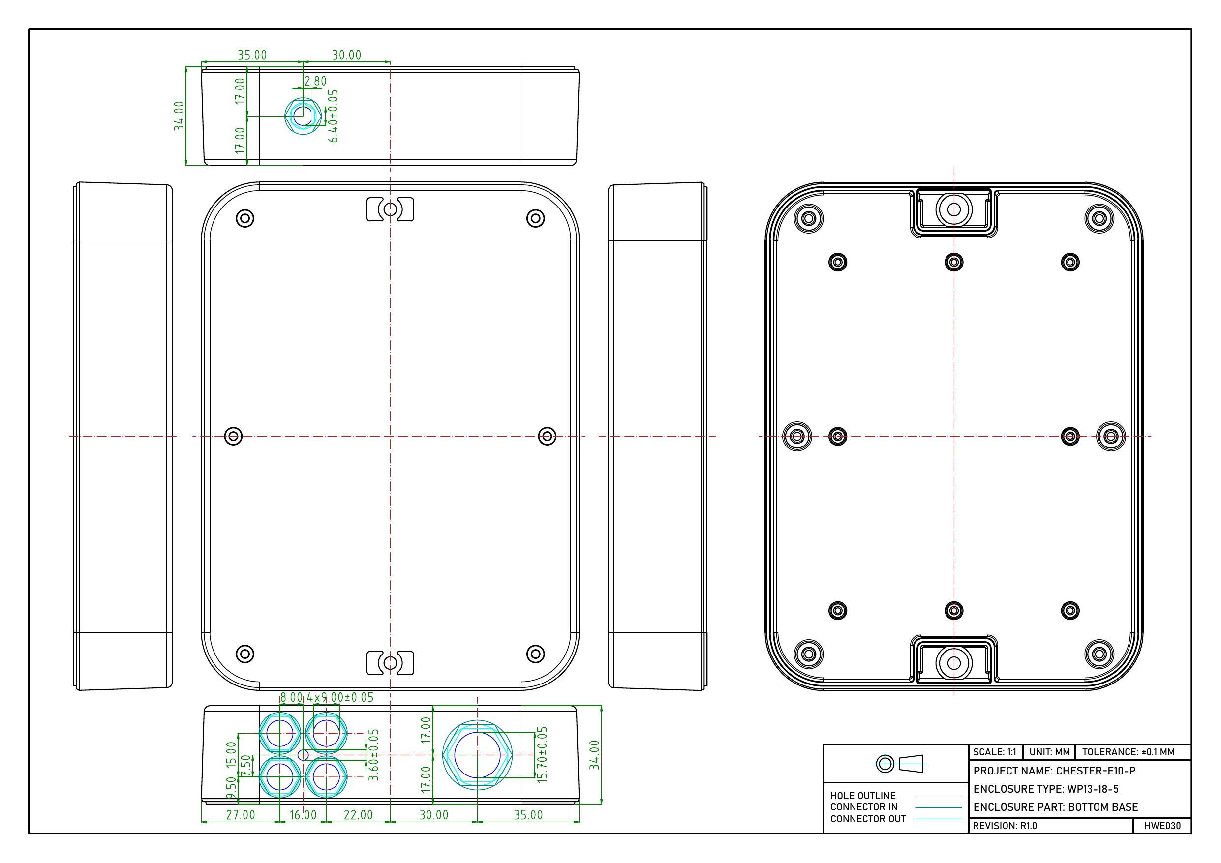
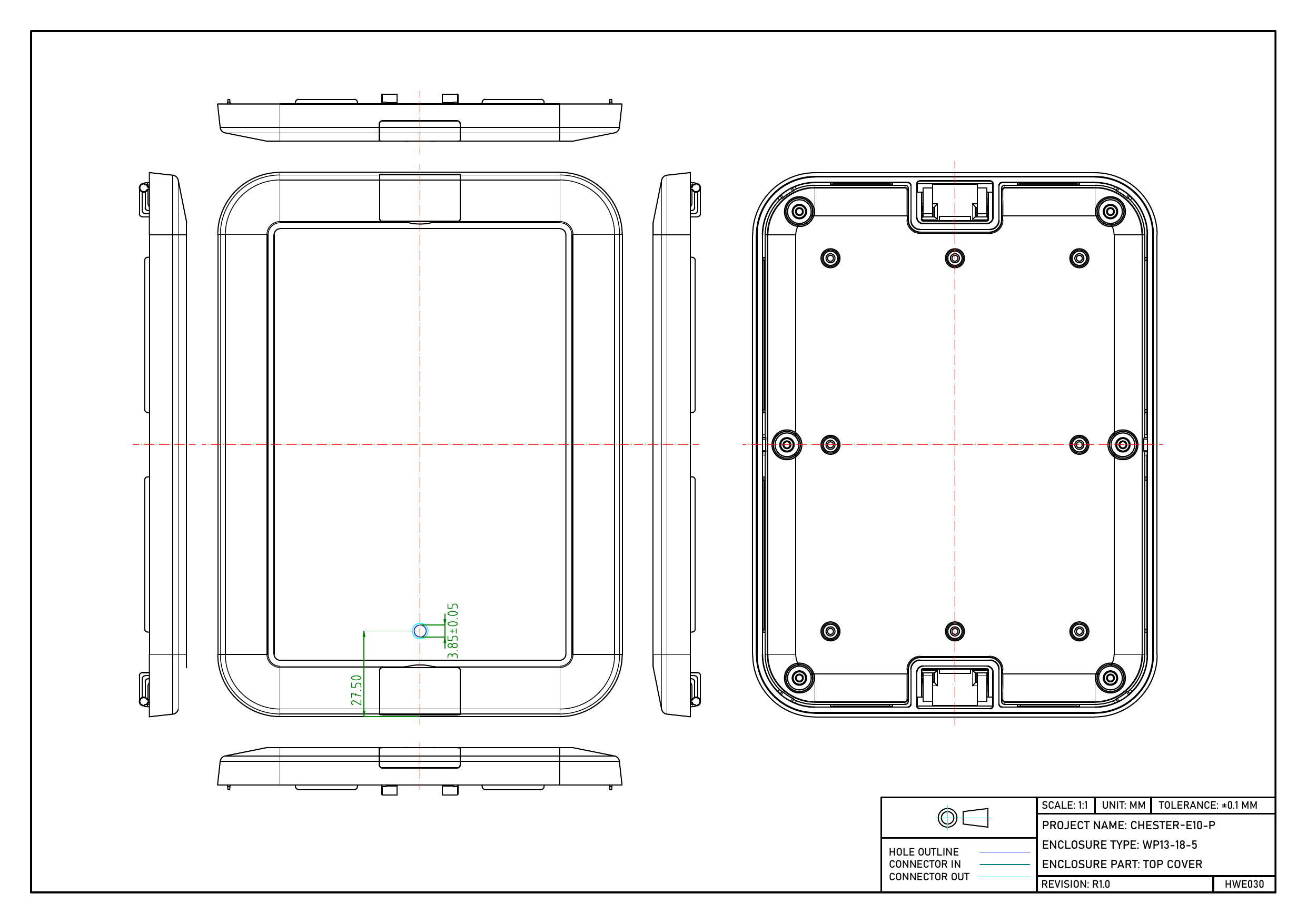
CHESTER-E10-P

Dimensioned drawing of the CHESTER-E10-P bottom base with machined hole positions Dimensioned drawing of the CHESTER-E10-P top cover with one small vent hole

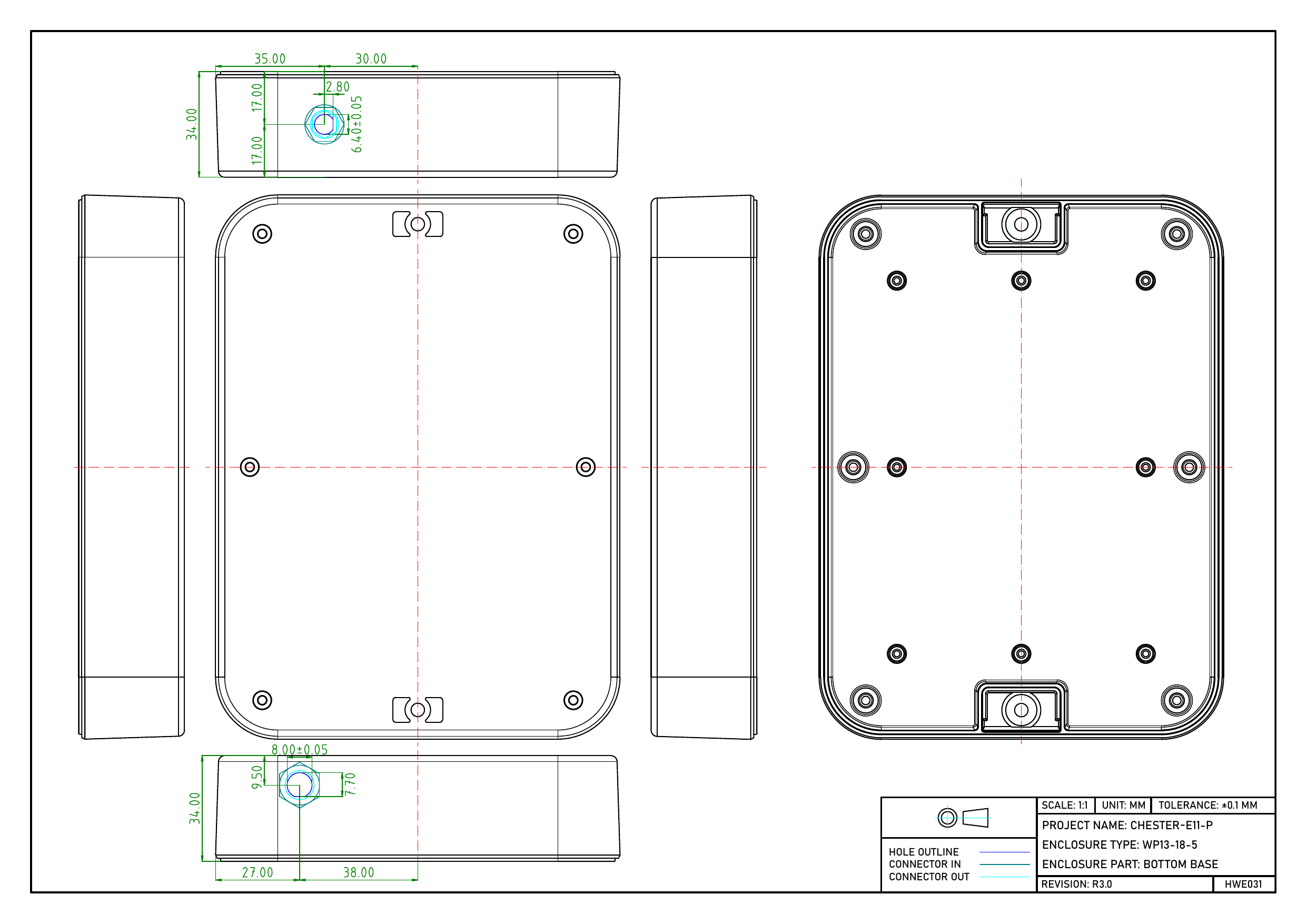
CHESTER-E11-P

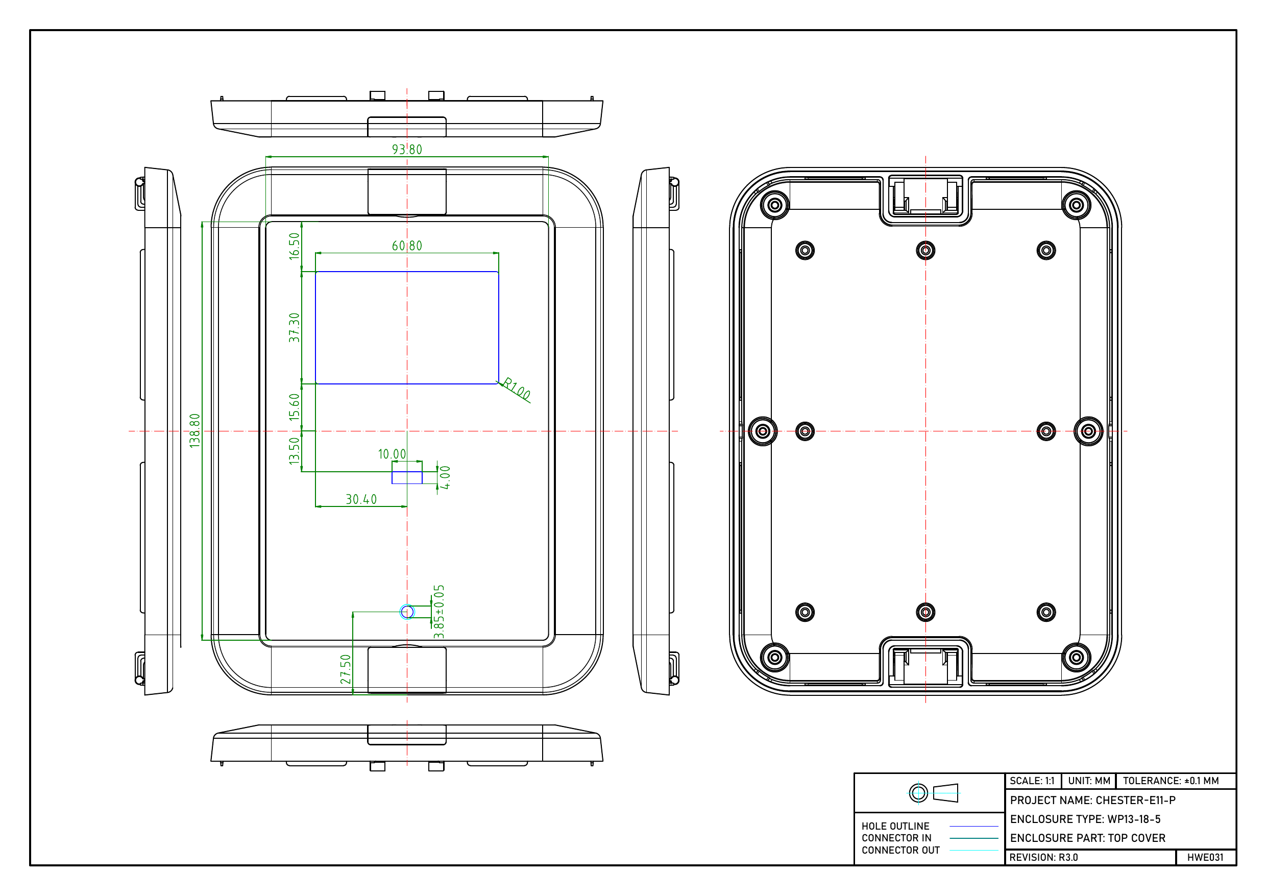
Dimensioned drawing of the CHESTER-E11-P bottom base with machined hole positions Dimensioned drawing of the CHESTER-E11-P top cover with the rectangular display window cutout

CHESTER-E12-P

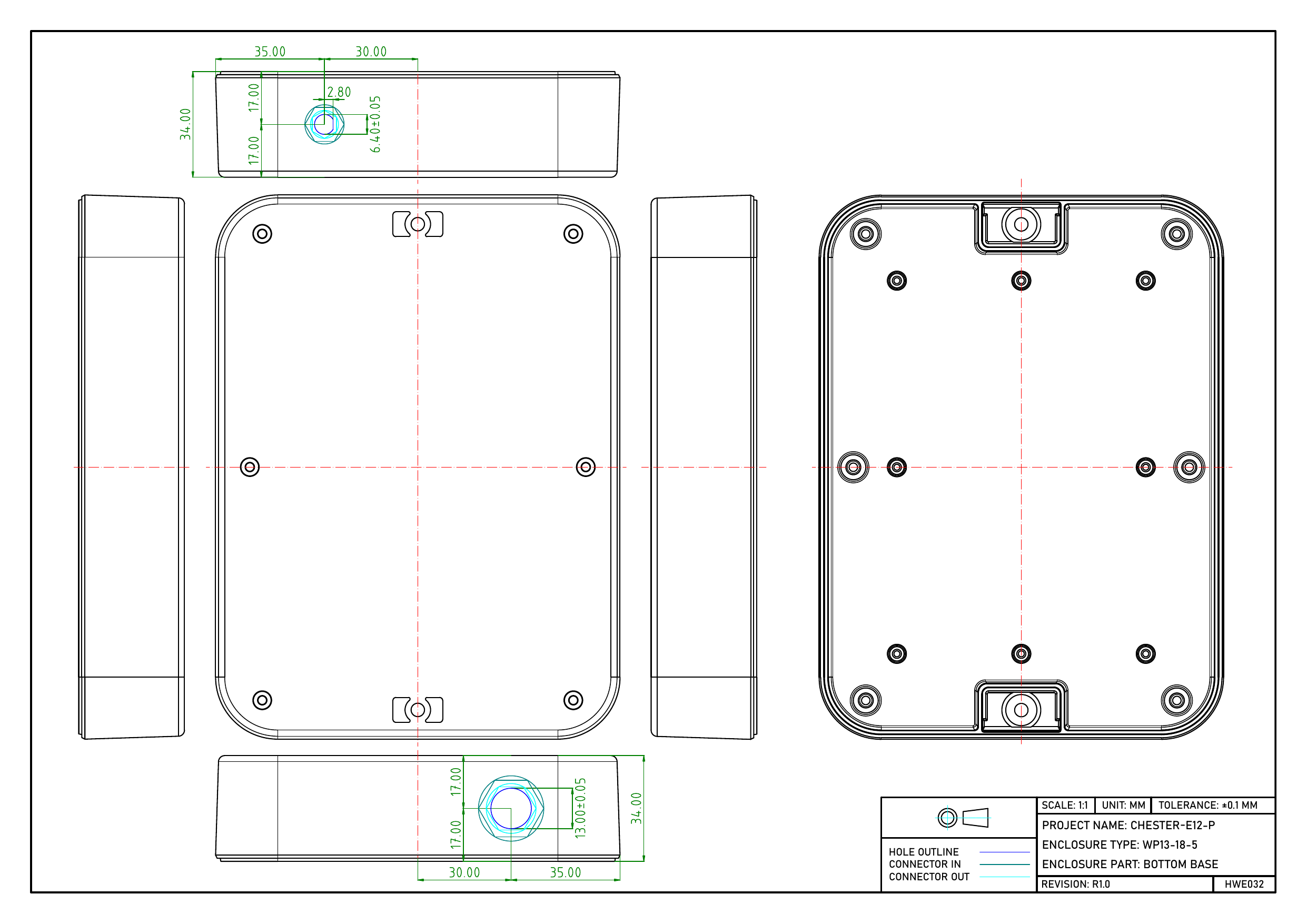
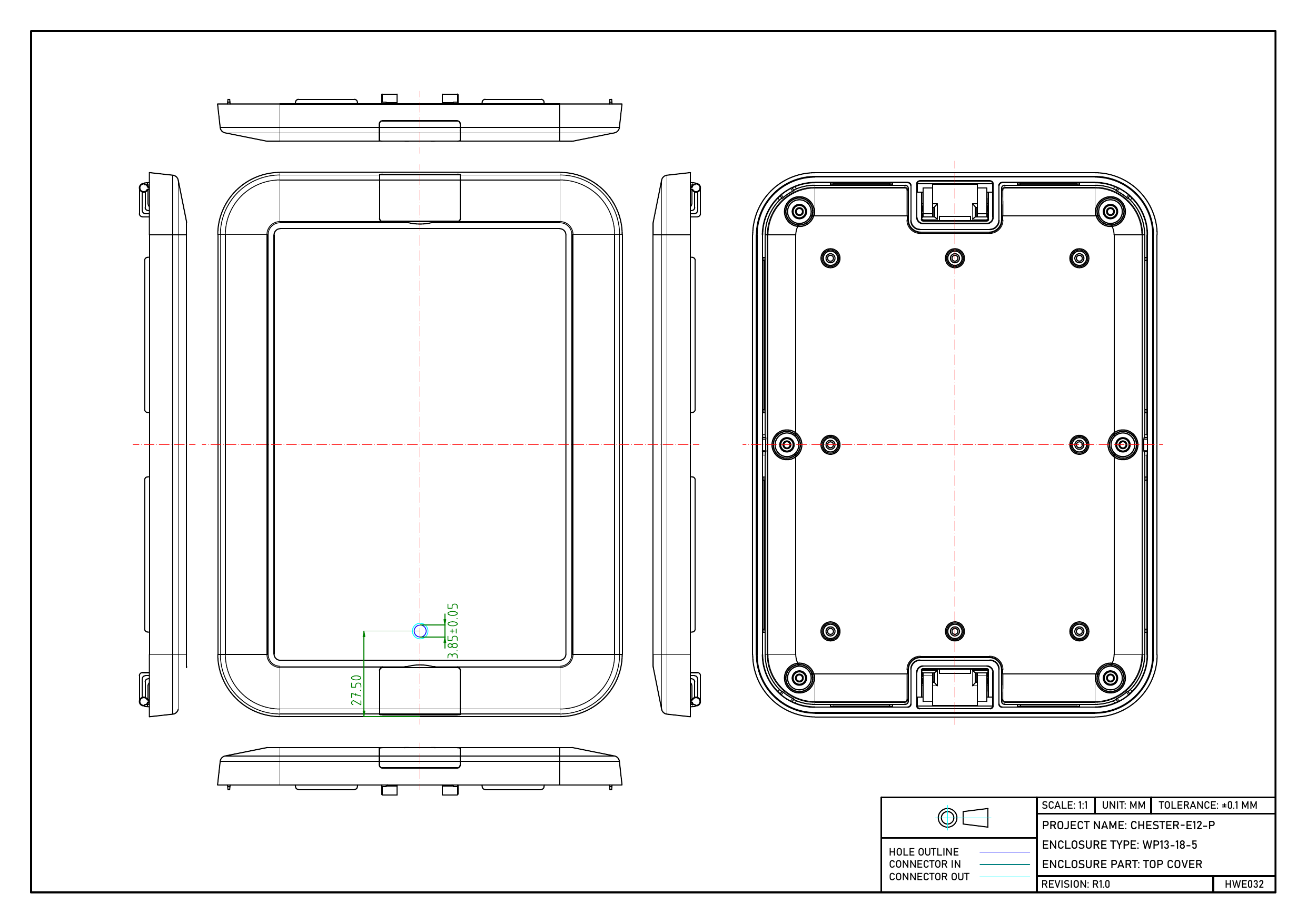
Dimensioned drawing of the CHESTER-E12-P bottom base with machined hole positions Dimensioned drawing of the CHESTER-E12-P top cover with machined hole positions

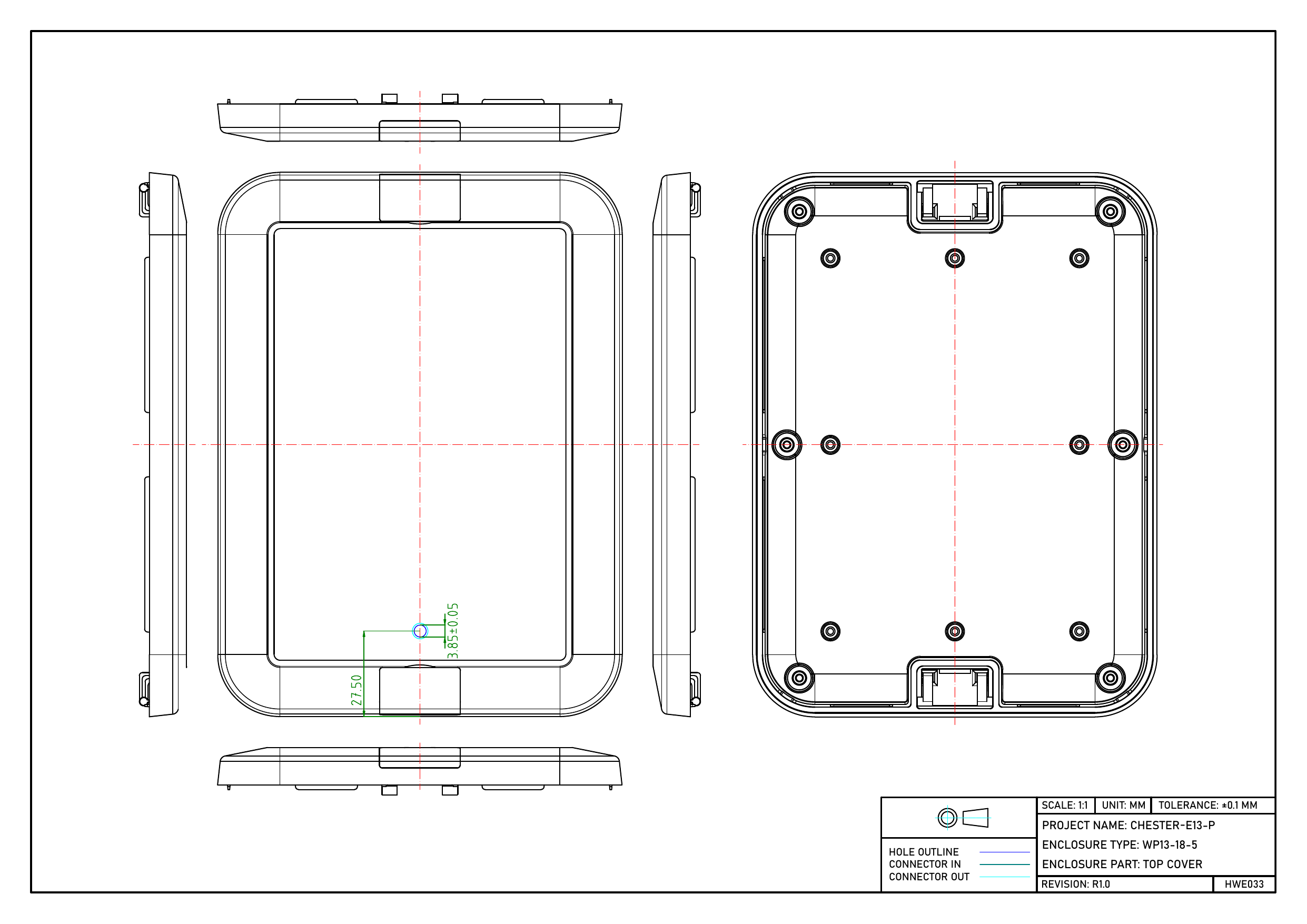
CHESTER-E13-P

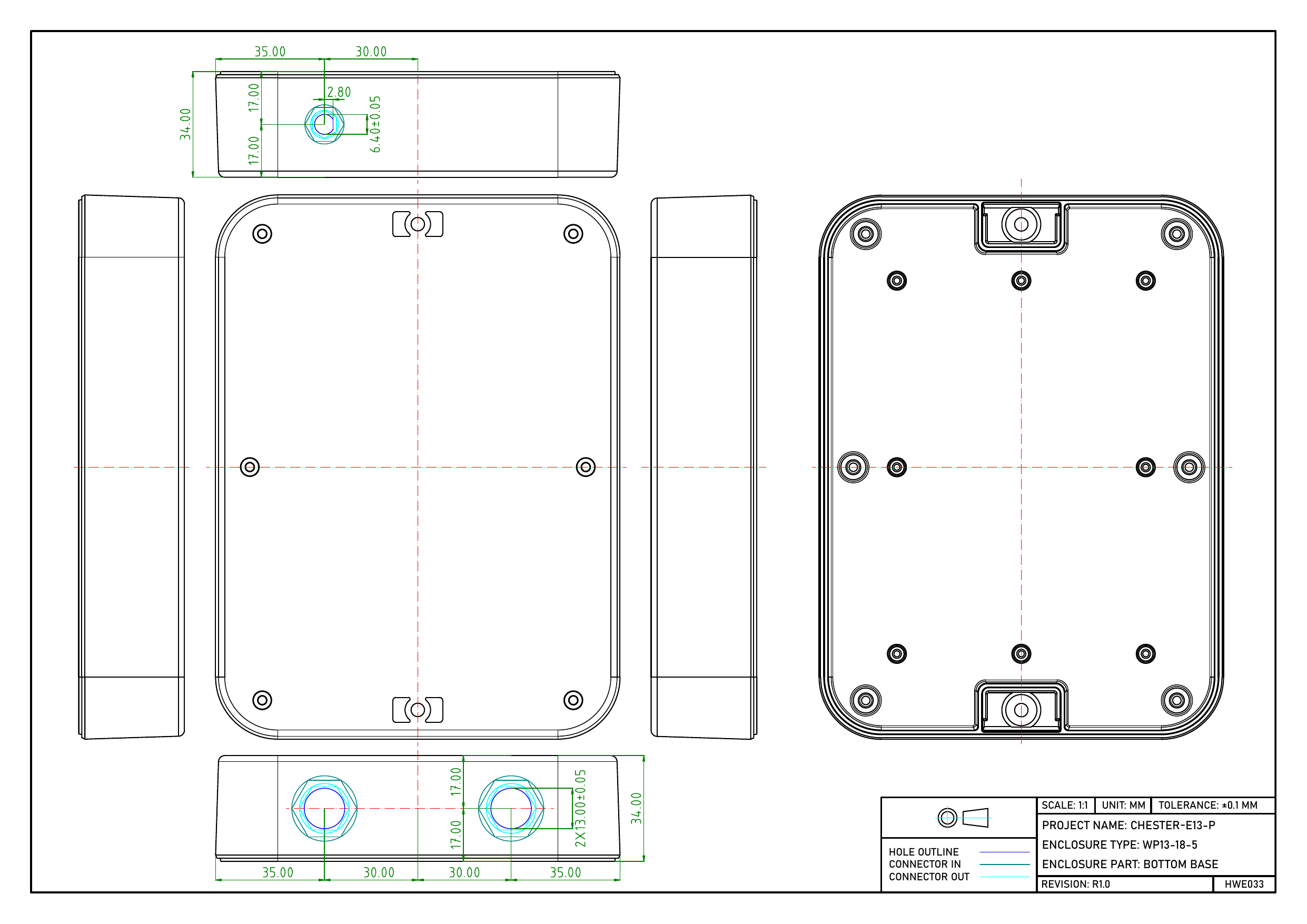
Dimensioned drawing of the CHESTER-E13-P bottom base with machined hole positions Dimensioned drawing of the CHESTER-E13-P top cover with machined hole positions

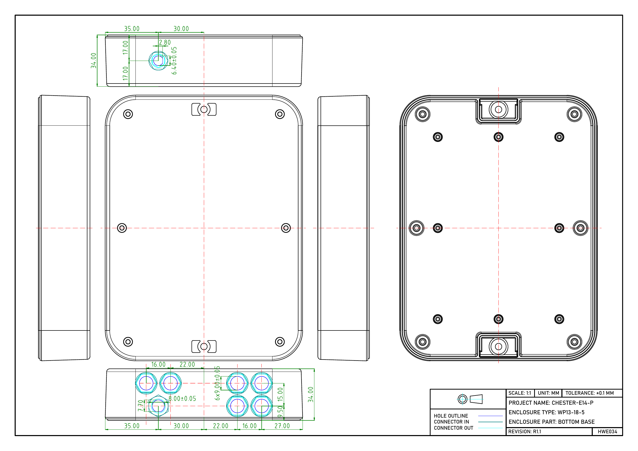
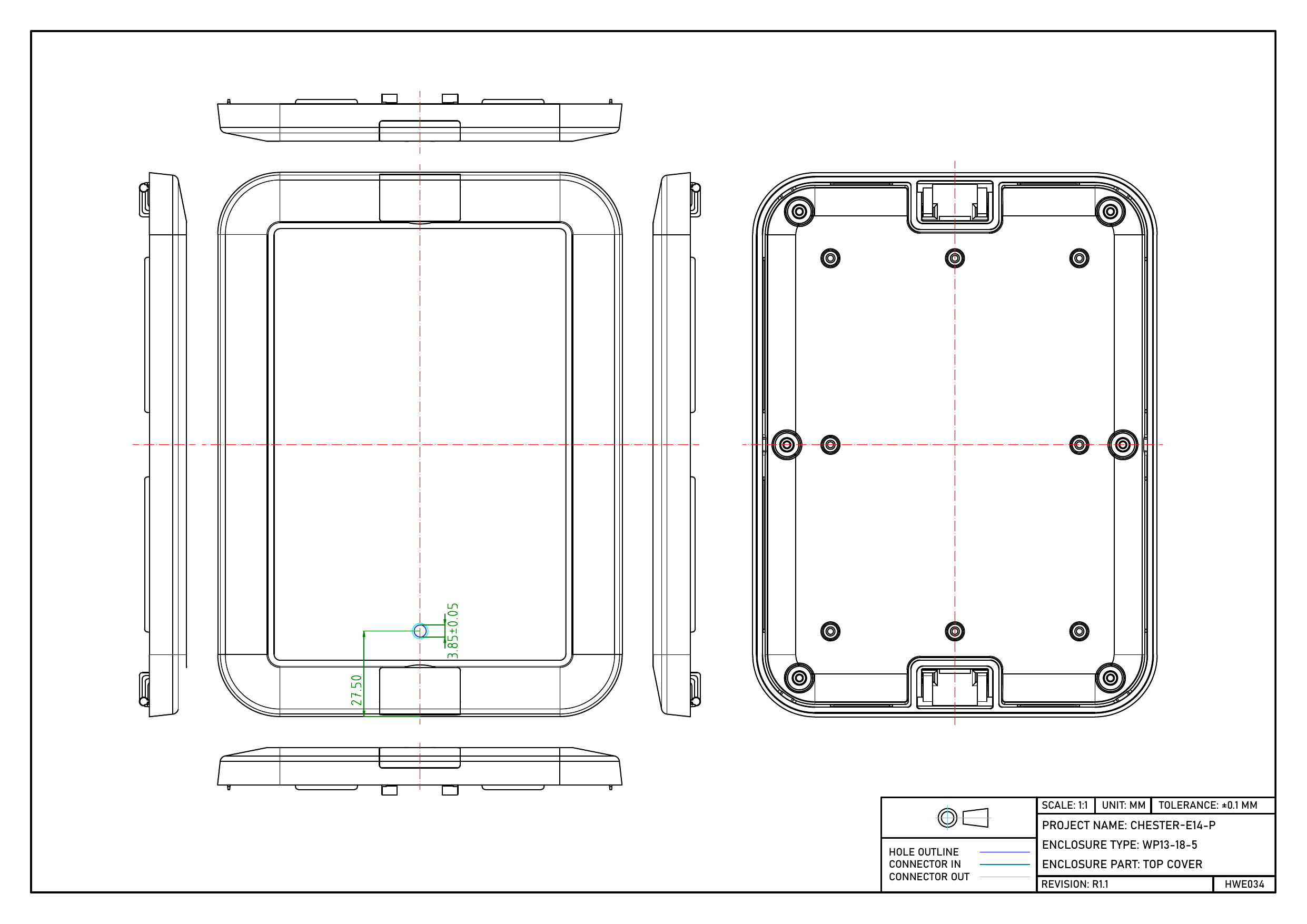
CHESTER-E14-P

Dimensioned drawing of the CHESTER-E14-P bottom base with machined hole positions Dimensioned drawing of the CHESTER-E14-P top cover with machined hole positions

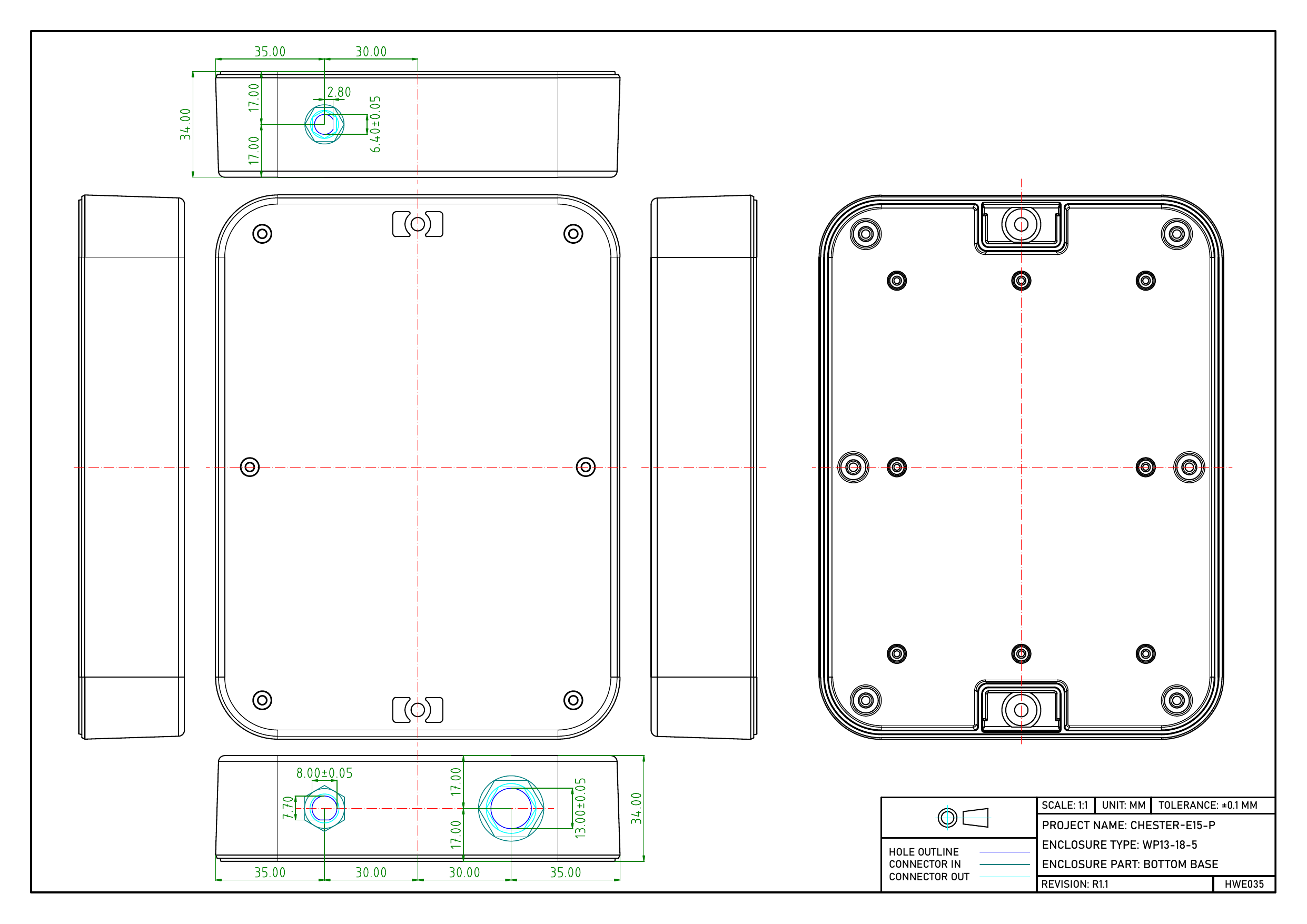
CHESTER-E15-P

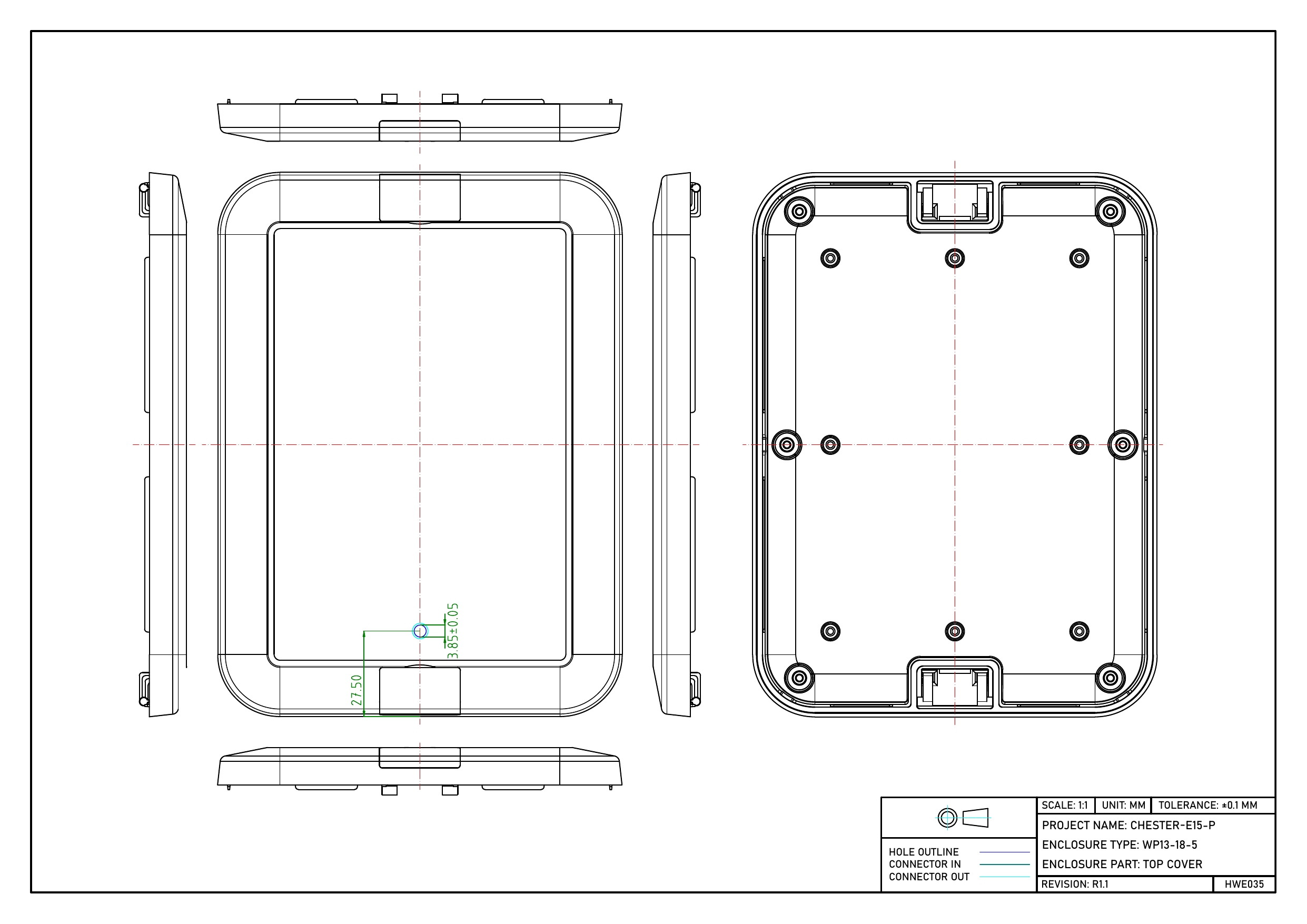
Dimensioned drawing of the CHESTER-E15-P bottom base with machined hole positions Dimensioned drawing of the CHESTER-E15-P top cover with machined hole positions

CHESTER-E16-P

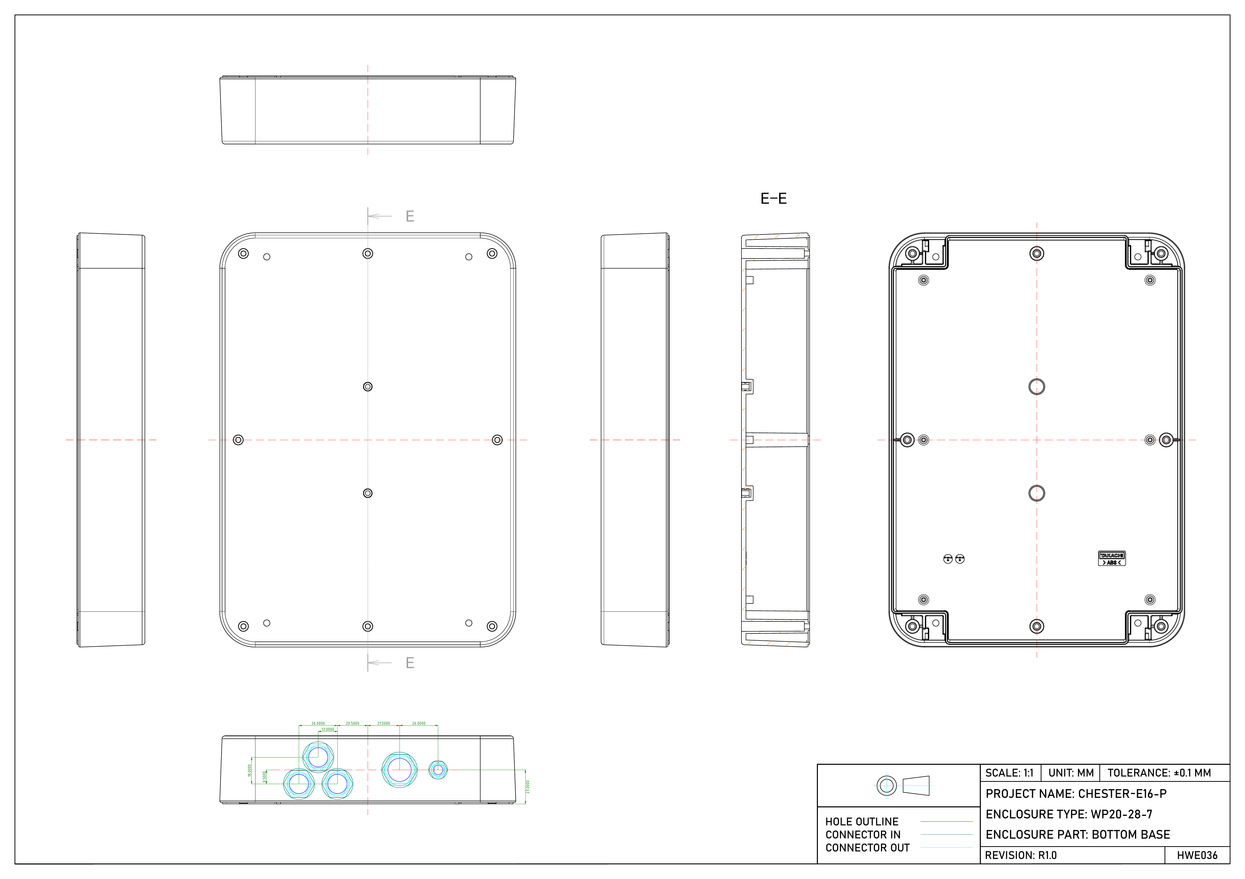
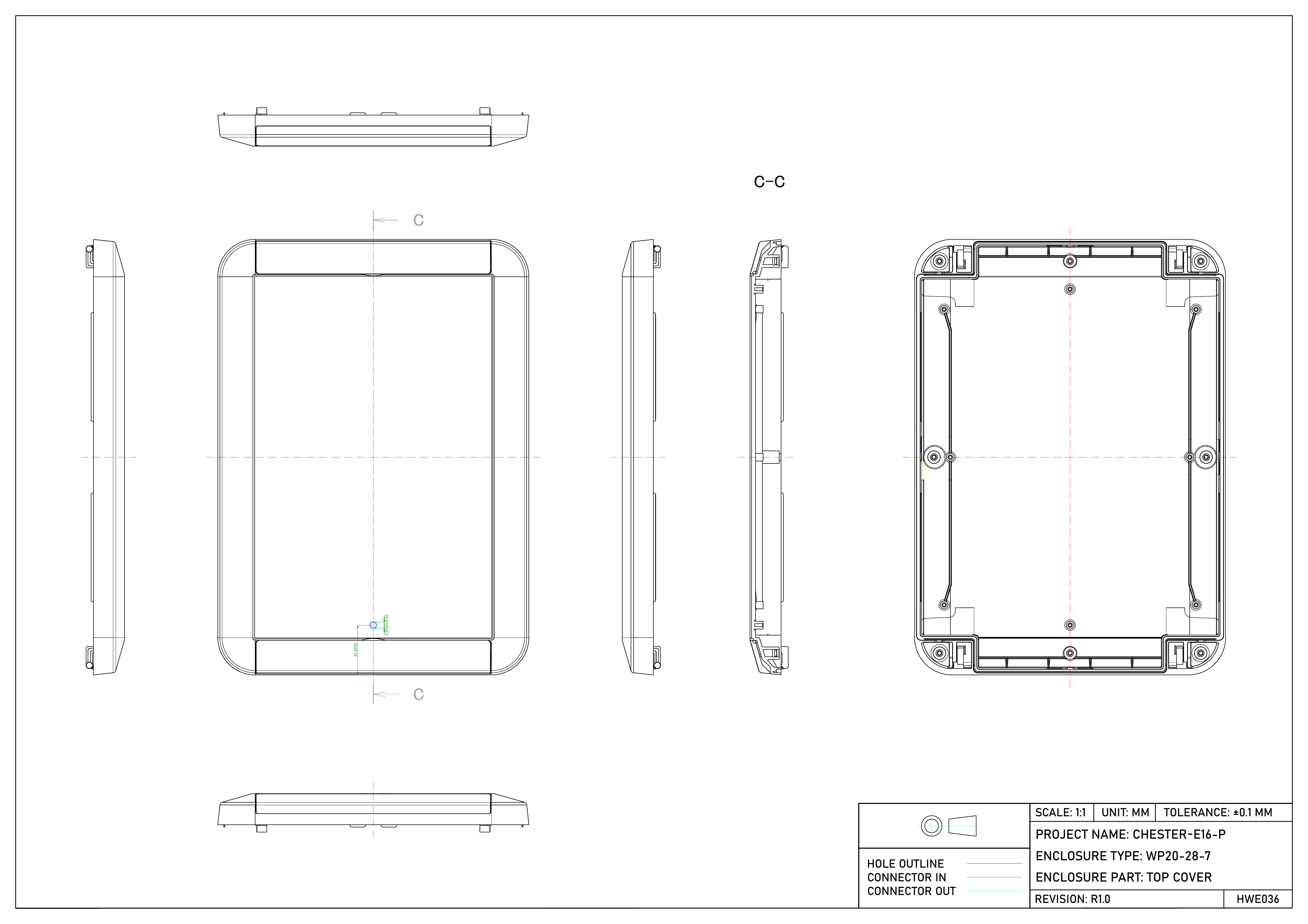
Dimensioned drawing of the CHESTER-E16-P bottom base with machined hole positions Dimensioned drawing of the CHESTER-E16-P top cover with machined hole positions

CHESTER-E17-P

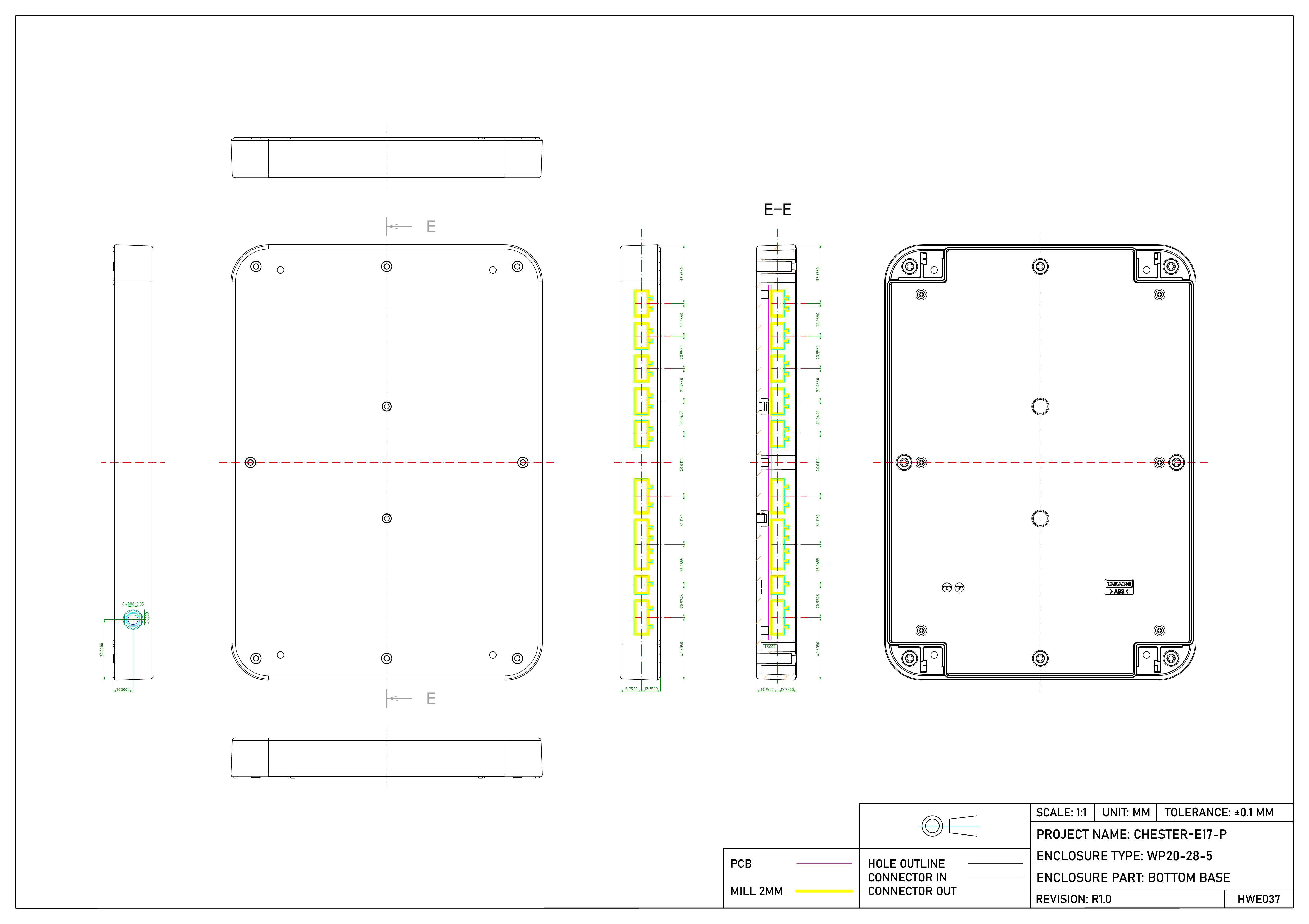
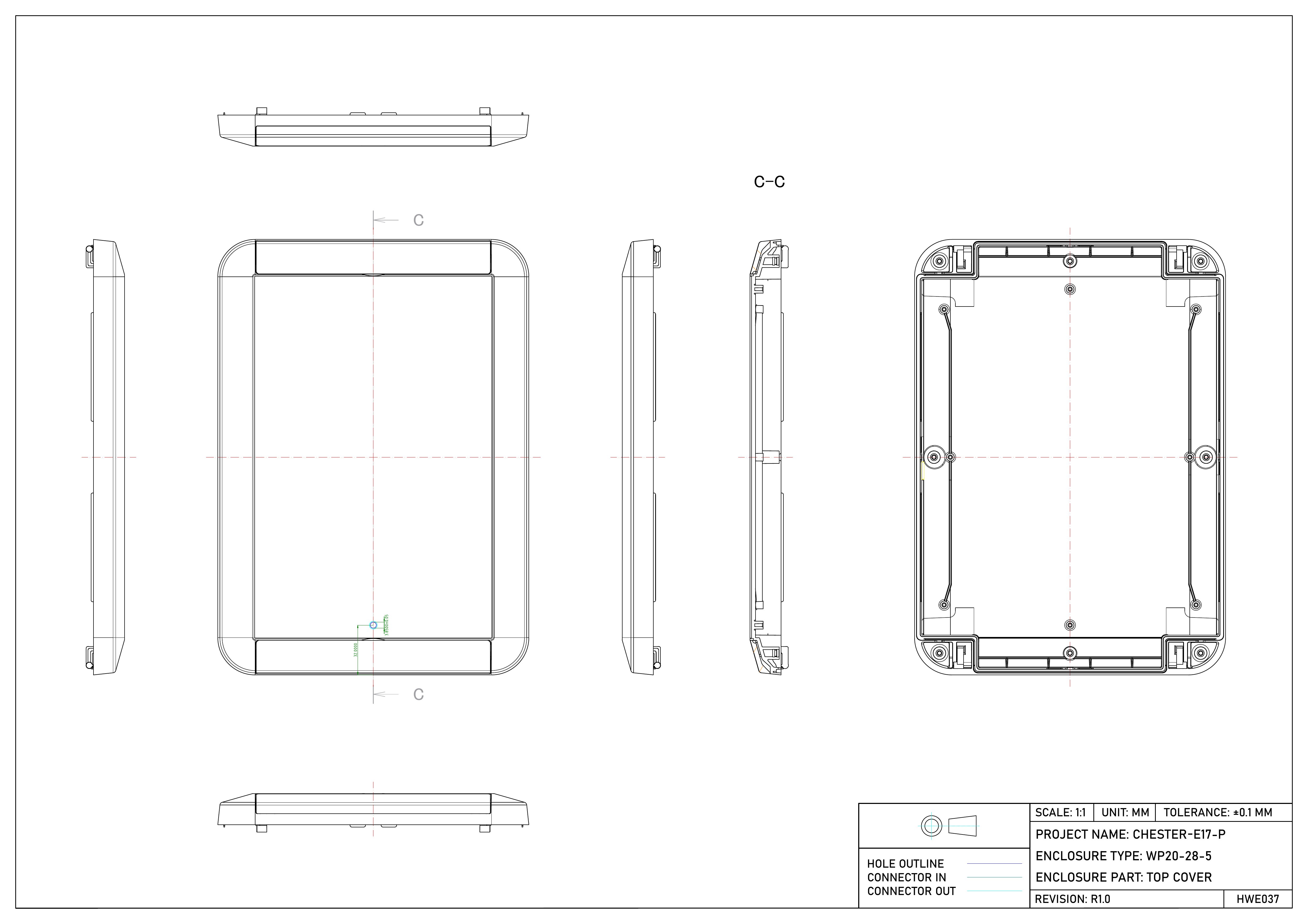
Dimensioned drawing of the larger CHESTER-E17-P bottom base with milled connector openings in the side walls Dimensioned drawing of the CHESTER-E17-P top cover with machined hole positions

CHESTER-E18-P

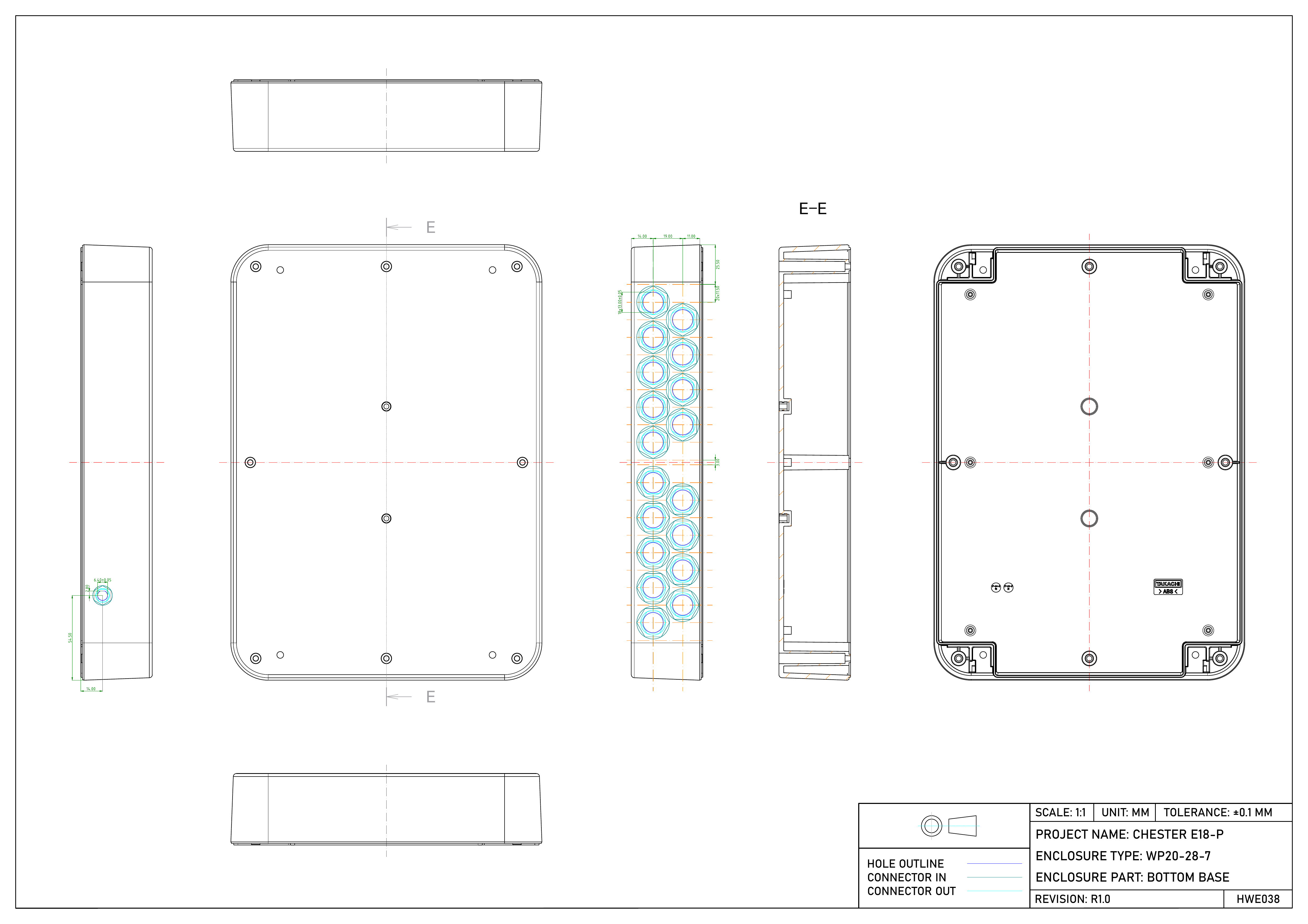
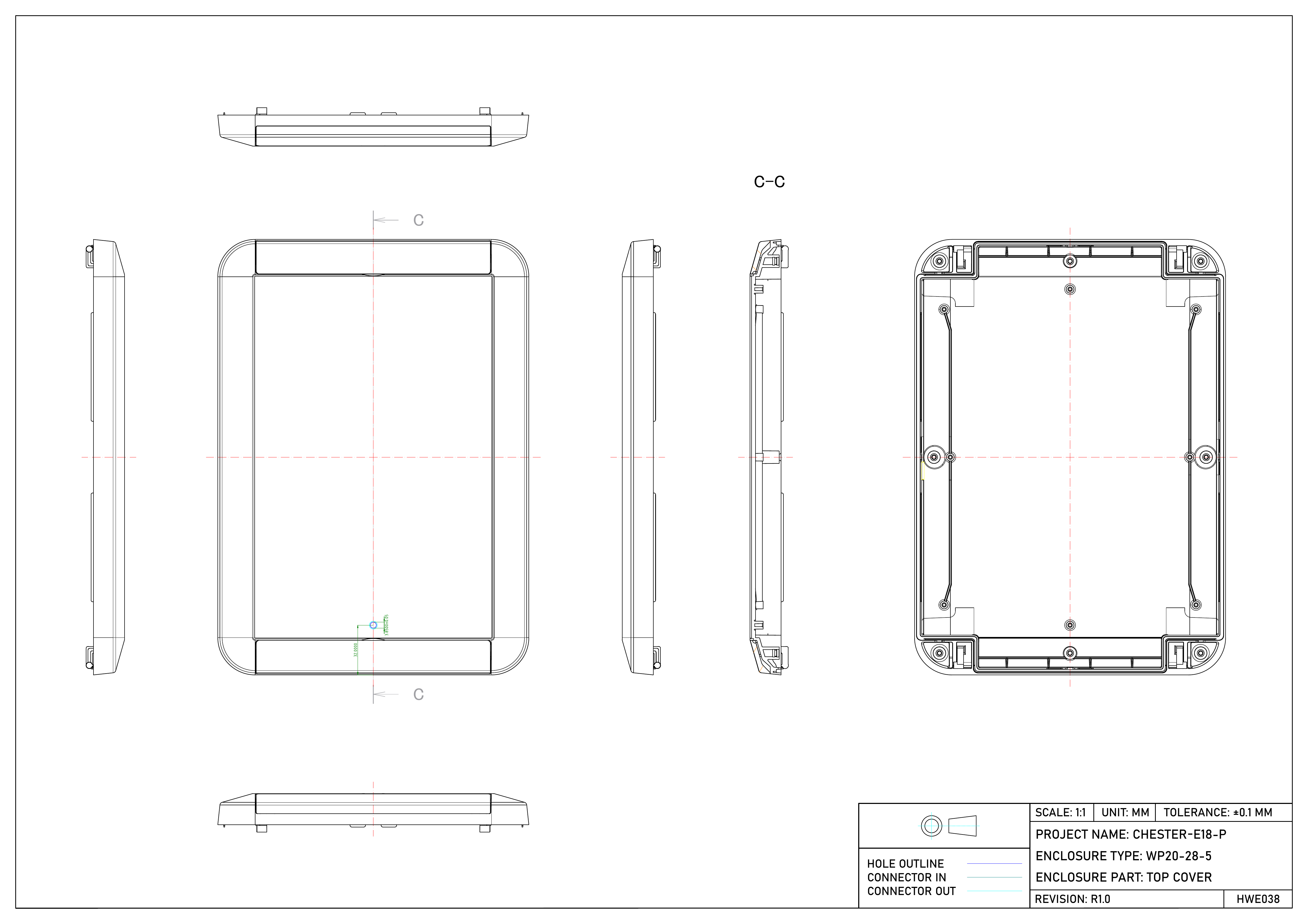
Dimensioned drawing of the larger CHESTER-E18-P bottom base with machined hole positions Dimensioned drawing of the CHESTER-E18-P top cover with machined hole positions

CHESTER-E19-P

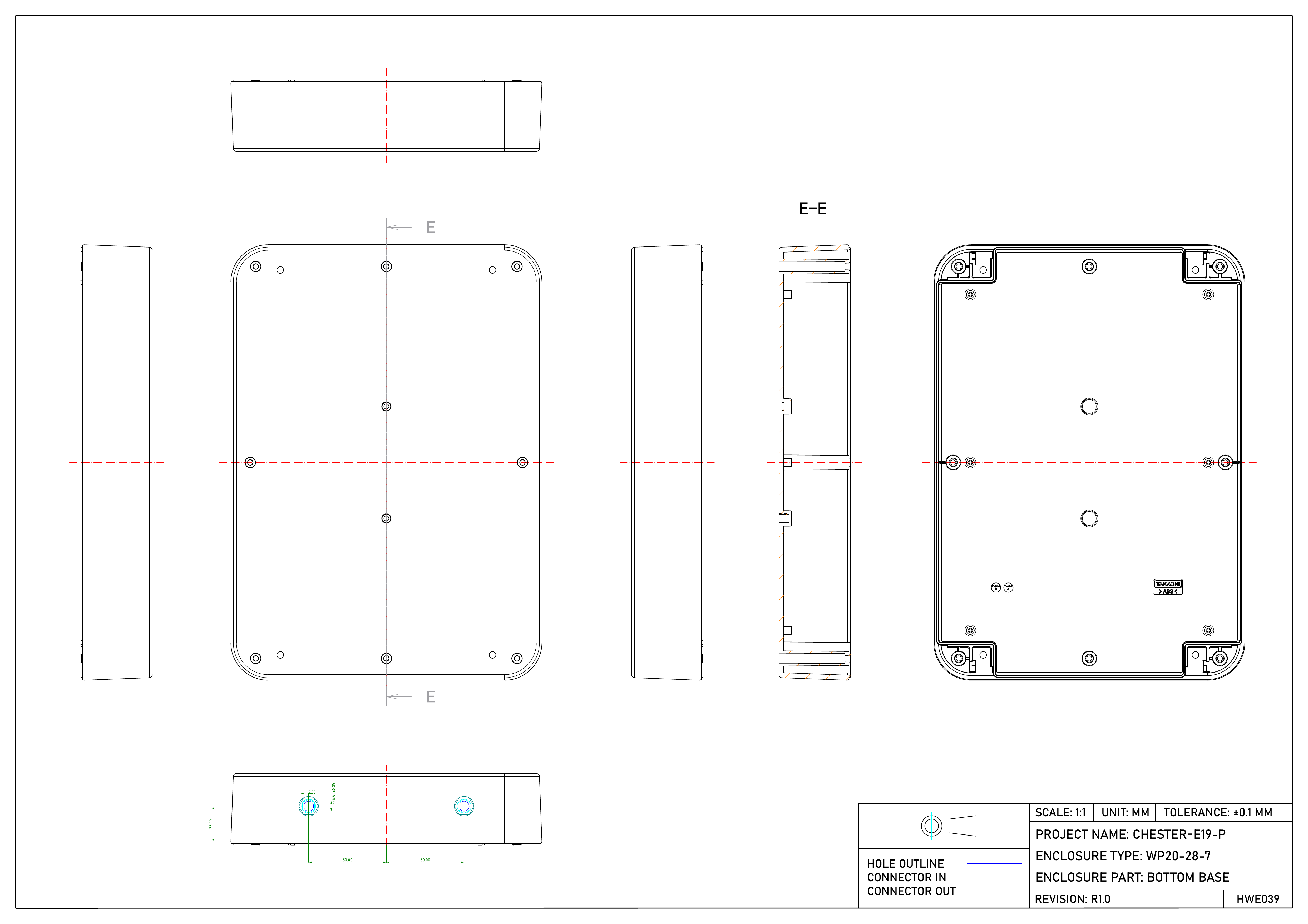
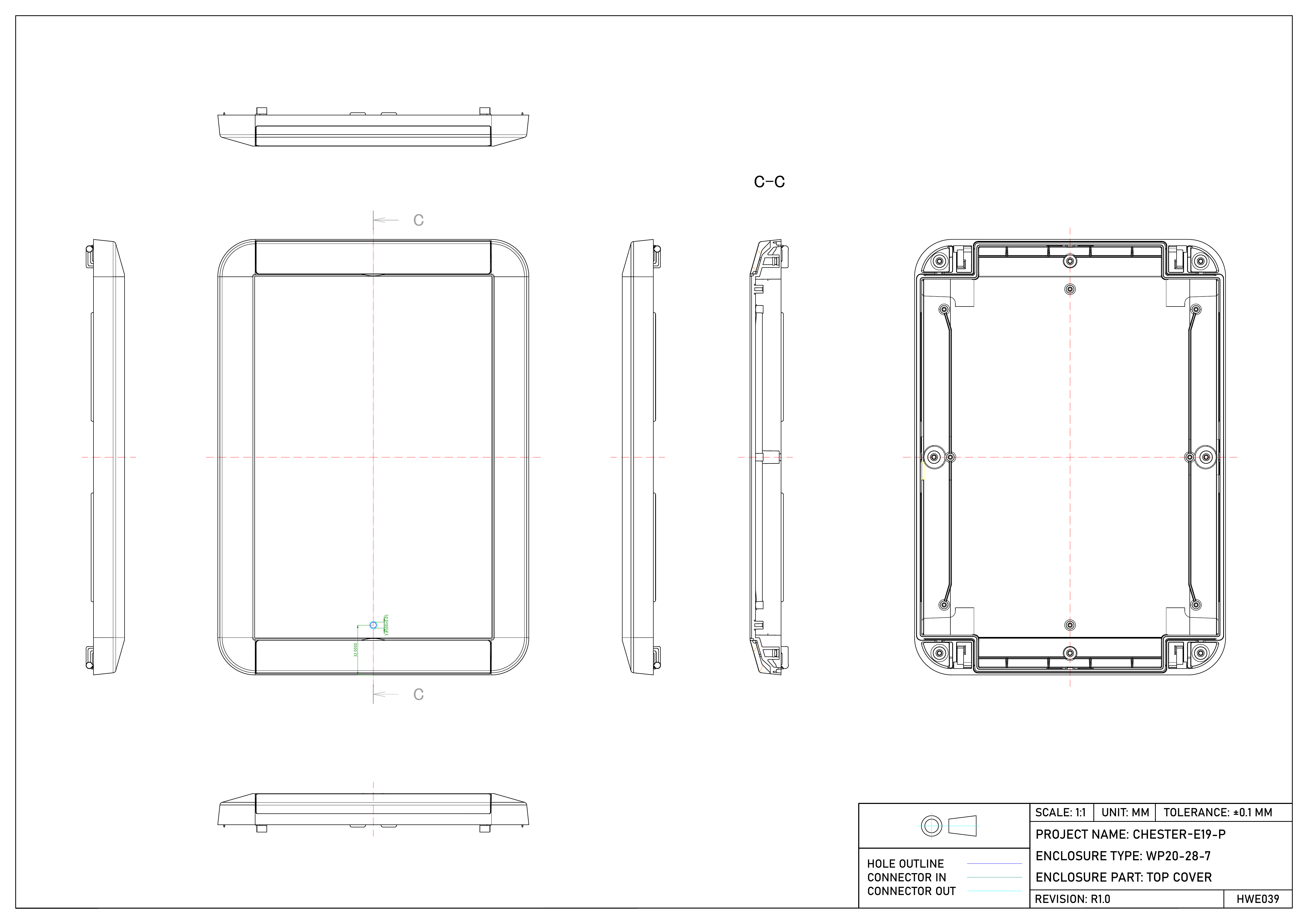
Dimensioned drawing of the larger CHESTER-E19-P bottom base with machined hole positions Dimensioned drawing of the CHESTER-E19-P top cover with machined hole positions