CHESTER-U1 Module
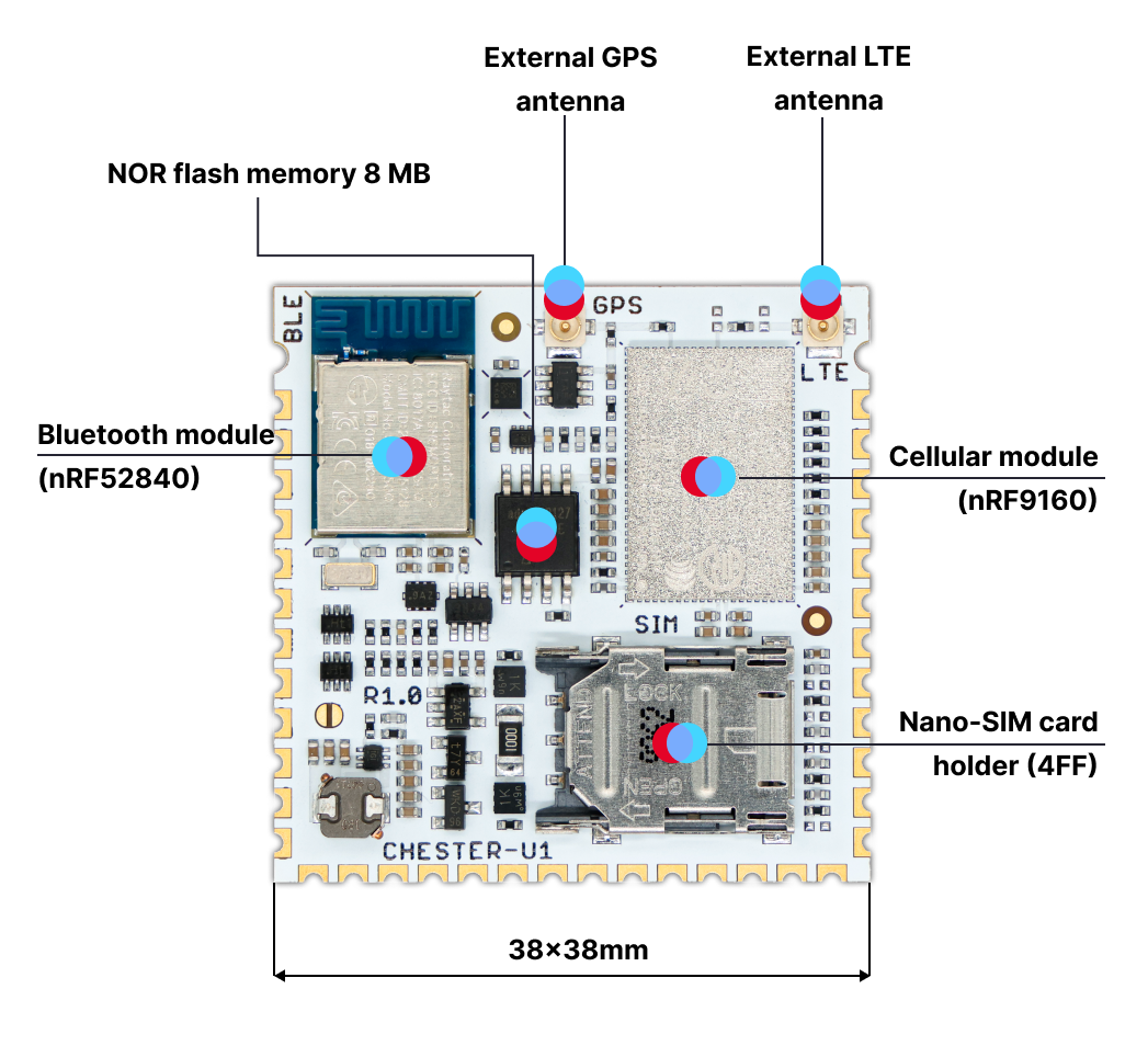
CHESTER-U1 is a cost-optimized CHESTER-M mainboard compressed to the small 38x38mm module.
Instead of using CHESTER-M and putting extension modules in it, you design a two-layer carrier board and put CHESTER-U1 in it.
CHESTER-U1 has these properties:
- Electrically identical to CHESTER-M (the same firmware binary can run without any changes)
- Cost-optimized
- Carrier board can be just a two-layer board
- Contains the same Application MCU (APP/BLE nRF52840) and LTE (nRF9160)
- Could be designed into smaller enclosures
- Can be connected to CHESTER-X extension modules the same way as CHESTER-M
- Contains a nano SIM card holder onboard
- Connect just a battery and u.FL antenna
E-CAD Library
HARDWARIO can provide ECAD footprints for your integration.
- KiCad symbol, footprint, 3D model
- Eagle CAD
Layout
Schematics
Interface
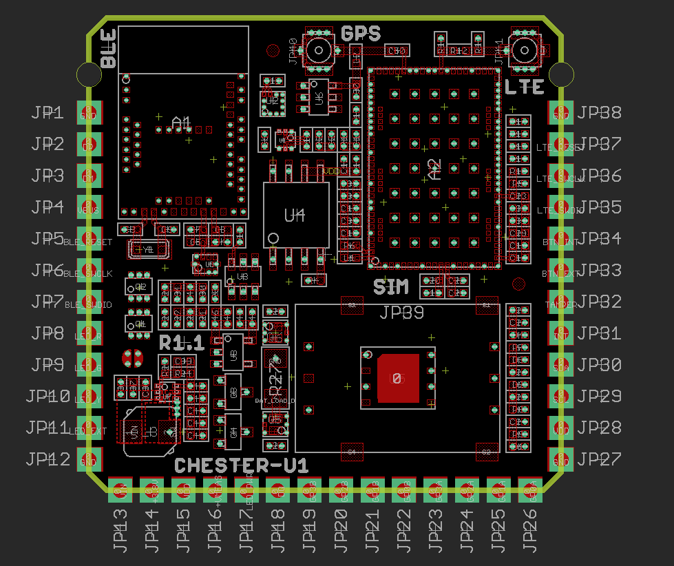
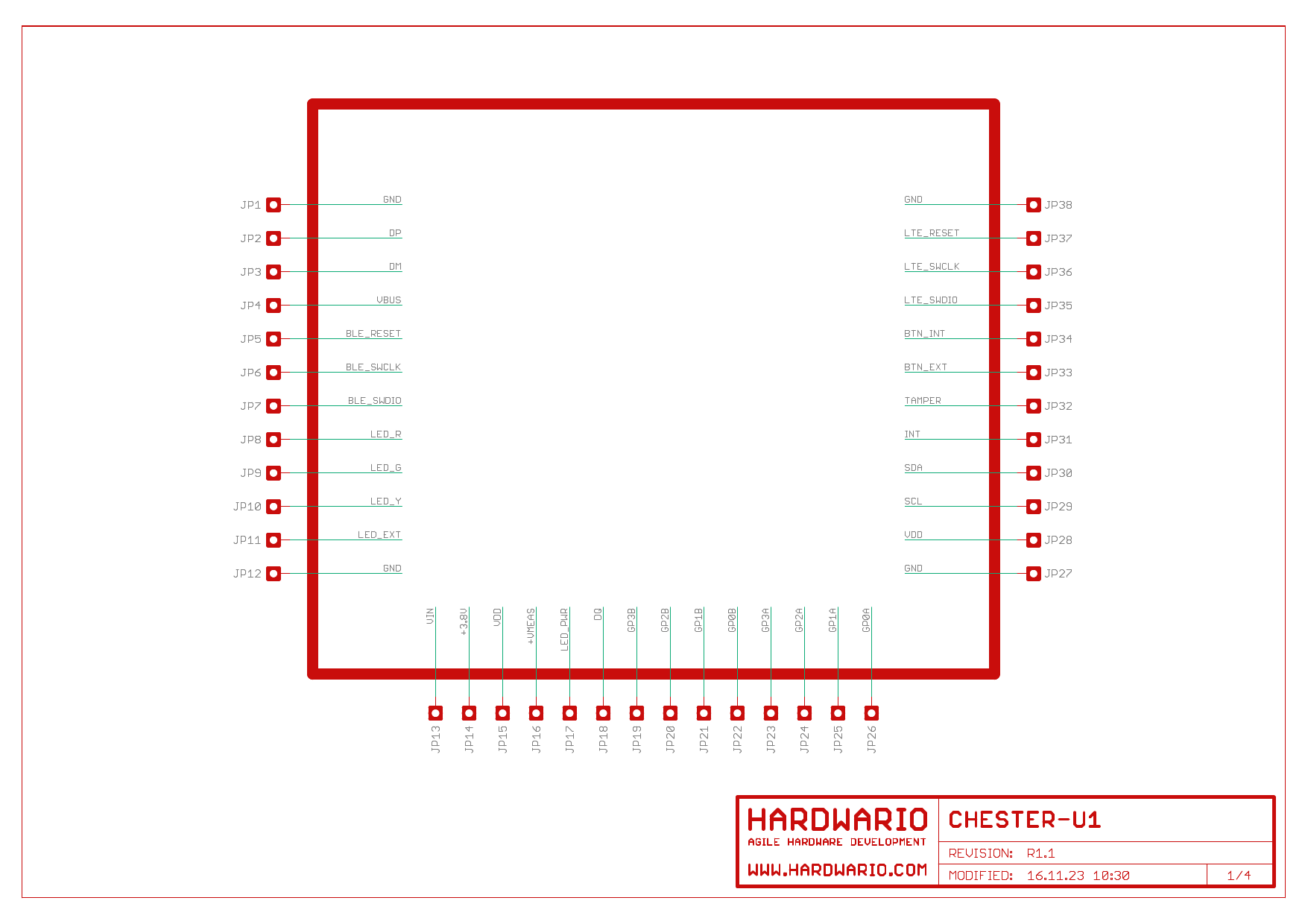
In this view, the signals are placed exactly as you look at the module from the top side. Signal placement has been optimized so you can easily route your wires on a two-layer printed circuit board.
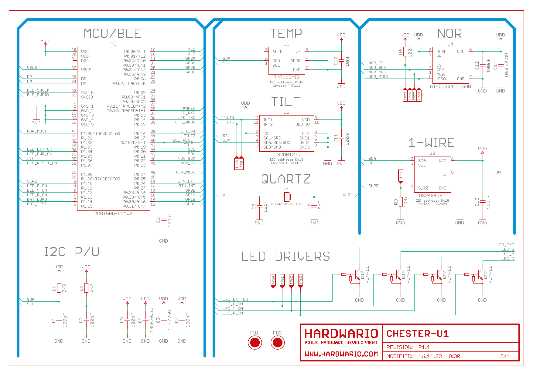
MCU
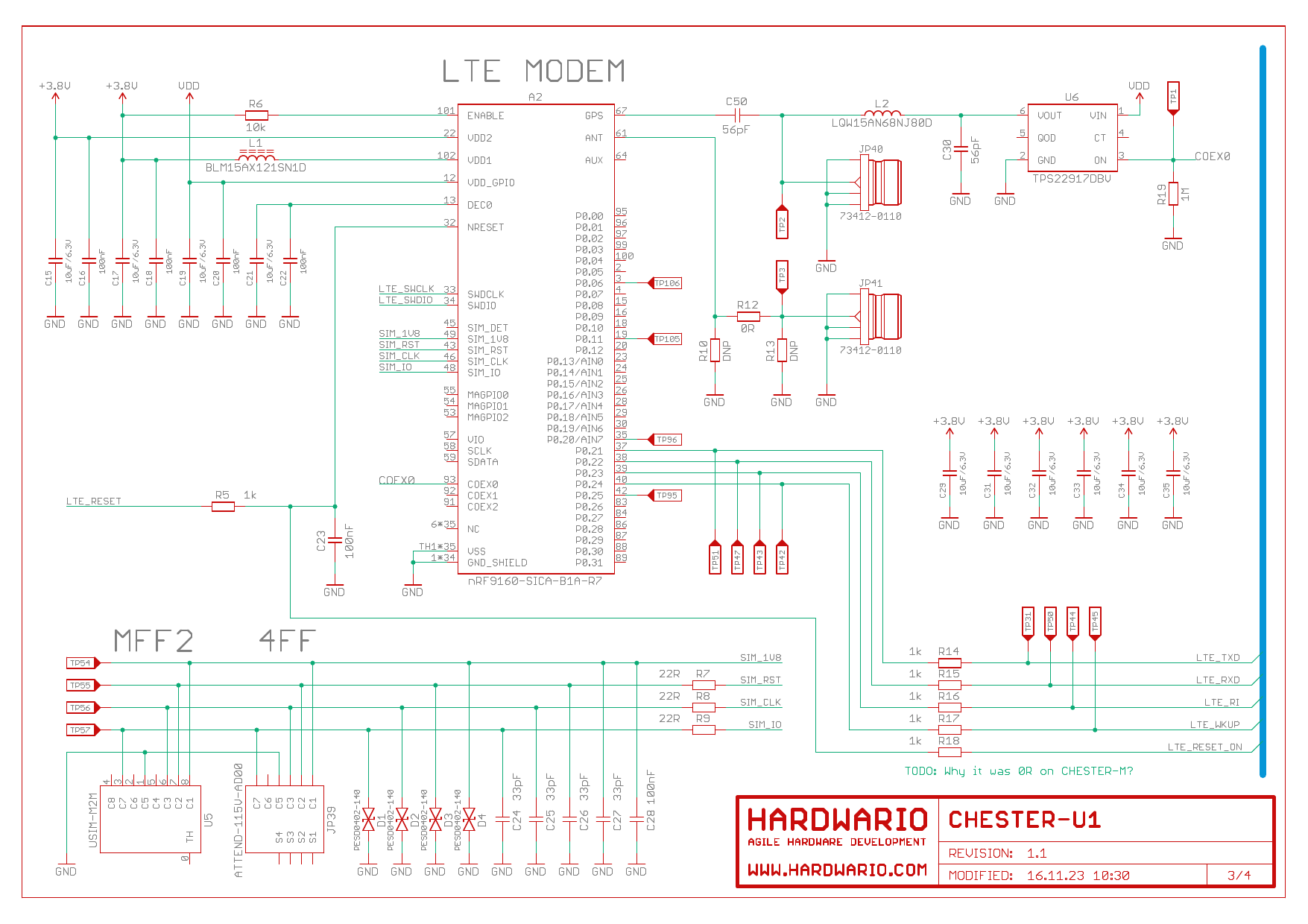
LTE
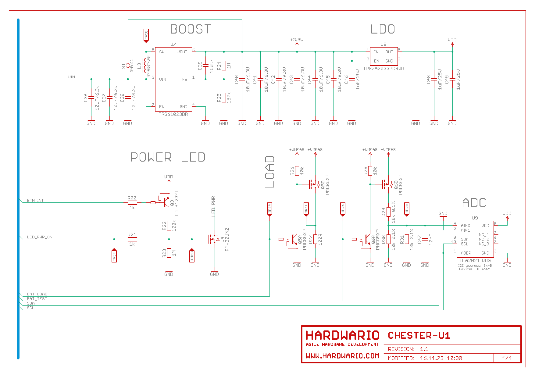
Power
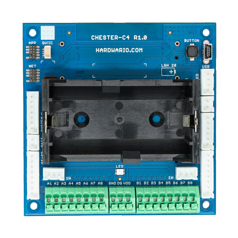
CHESTER-C4 Carrier Board
We have carrier boards that can be used directly in your product with CHESTER-U1 or you can base your own design on them. Get in touch with us, we can provide you with more information.
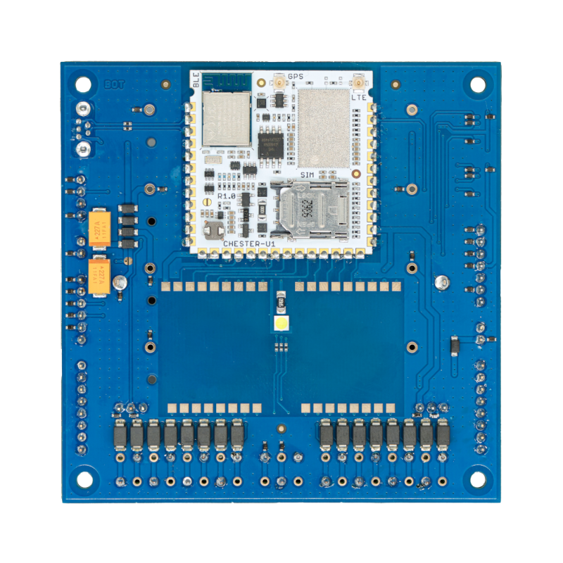
One of the carrier boards is CHESTER-C4, it contains a slot for two extension modules and can have multiple battery or external power options.
Bottom Side
Top Side
With "D" cell option.