Configuring a STICKER
This guide walks through configuring a STICKER with HARDWARIO Manager over NFC — from adding the device to writing settings and reading them back. If you have not installed the app yet, start with the Setup guide; for everything the app can do, see Features.
STICKER can be configured even with no batteries inserted. The NFC field from the phone powers the chip long enough to store settings; the device applies them the next time it wakes on battery power.
Before you begin
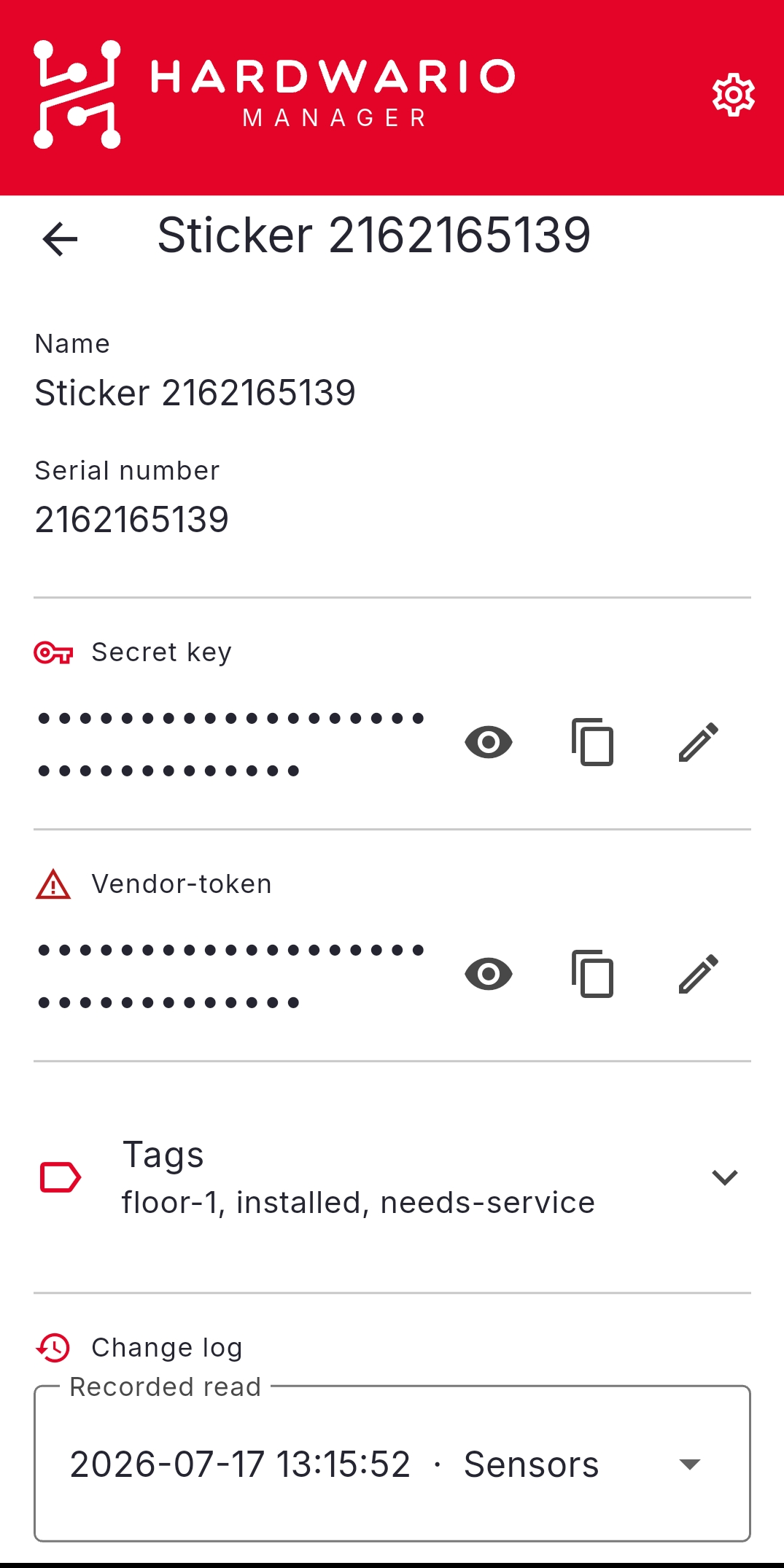
Each STICKER talks over an encrypted NFC channel, so the app needs the device's secret key before it can read or write. You add a device once and the app remembers it.
- Open HARDWARIO Manager and go to STICKER → Saved Stickers.
- Add your device by tapping it over NFC, scanning its QR code, or entering its details by hand.
- Enter the secret key supplied with the device.
From now on the app fills the key in automatically whenever you work with that STICKER.
Write a configuration
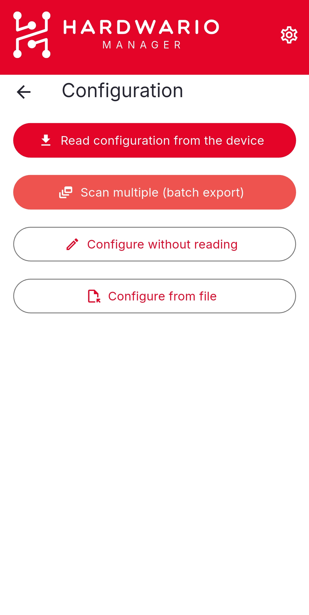
Go to STICKER → Configuration and choose Read configuration from the device. The other entry actions handle batch export, writing to a powered-off device, and loading a saved file.
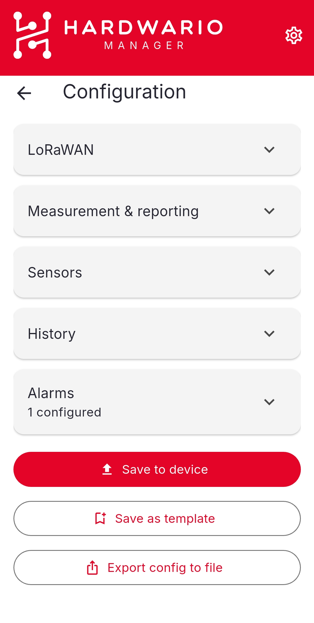
Hold the phone against the STICKER until the current configuration is read, then open the section you want to change — LoRaWAN (region, activation, EUIs and keys), Measurement & reporting (sample and report intervals), Sensors, History, Alarms, or Keys.
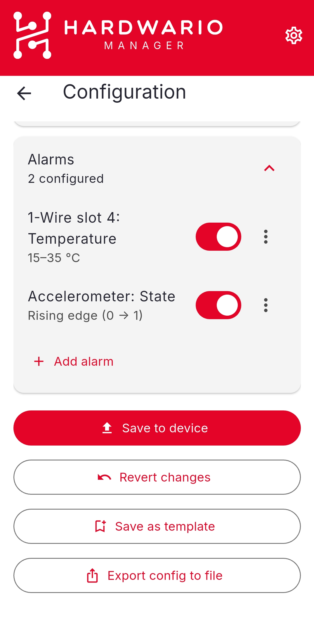
Edit the settings you need — for example toggle or adjust an alarm rule — then tap Save to device and hold the phone against the STICKER again to write the changes. Use Revert changes to discard edits, or Export config to file to keep a copy.
For every parameter and its meaning, see Configuration parameters →.
Read a configuration
To check what is on a device, go to STICKER → Configuration → Read configuration from the device and hold the phone against the STICKER. The current settings are shown for review — nothing is written until you tap Save to device.
Configure a powered-off device
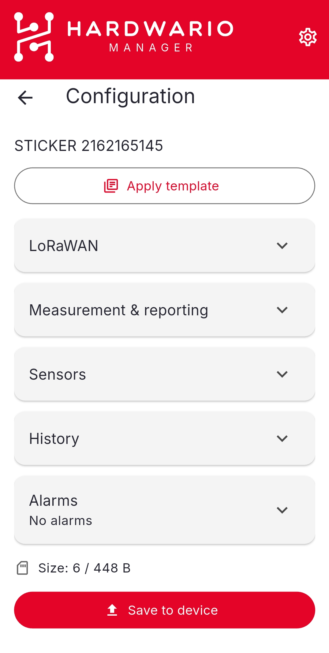
To prepare a STICKER that has no batteries, use STICKER → Configuration → Configure without reading. Build the configuration — Apply template, or open each section and set the values (the size counter shows how much of the tag's budget you've used) — then tap Save to device and hold the phone against the STICKER. The phone's NFC field powers the tag and stores the settings, which the device applies on its next boot.
Reuse a configuration across devices
To set up many STICKERs the same way, save a template (Configuration → Save as template, or STICKER → Templates) and apply it to each device over NFC or offline. You can also build a template in a browser with the Template Generator.
A factory reset (under STICKER → Tools → Reset) drops the device's LoRaWAN session and keys, so it re-joins the network; a vendor reset wipes it back to its serial number and vendor token (and sets a new secret key). There is no undo.
Troubleshooting
| Problem | What to check |
|---|---|
| The STICKER will not read | NFC is on, no thick case, hold the top-back of the phone flat against the tag and keep still for a few seconds. |
| A write seems to do nothing | The device silently ignores writes made with the wrong secret key. Confirm the saved secret key for this device is correct. |
| The configuration is too large | Reduce the number of settings — the app shows the size against the device's limit. |
| No response after a LoRaWAN join | Verify the keys and device profile in your network server. |