Hardware Description
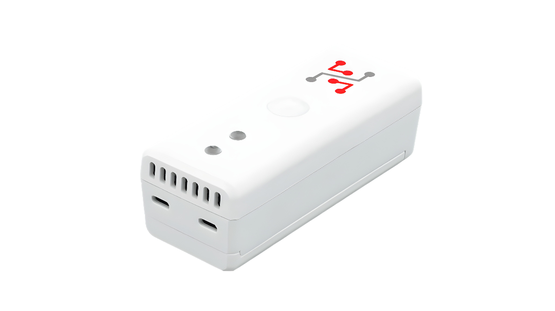
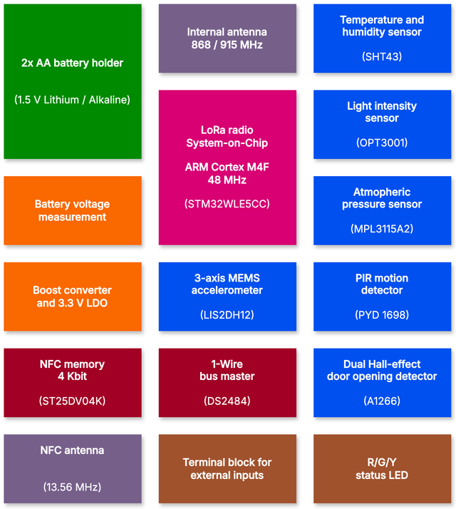
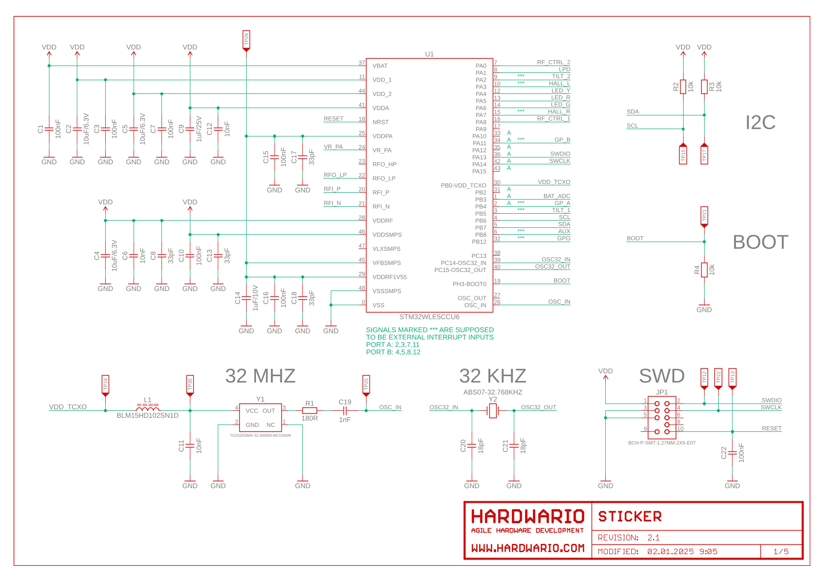
STICKER is a compact IoT device built on the STM32WL System-on-Chip with an integrated LoRa radio and ARM Cortex-M4F core.
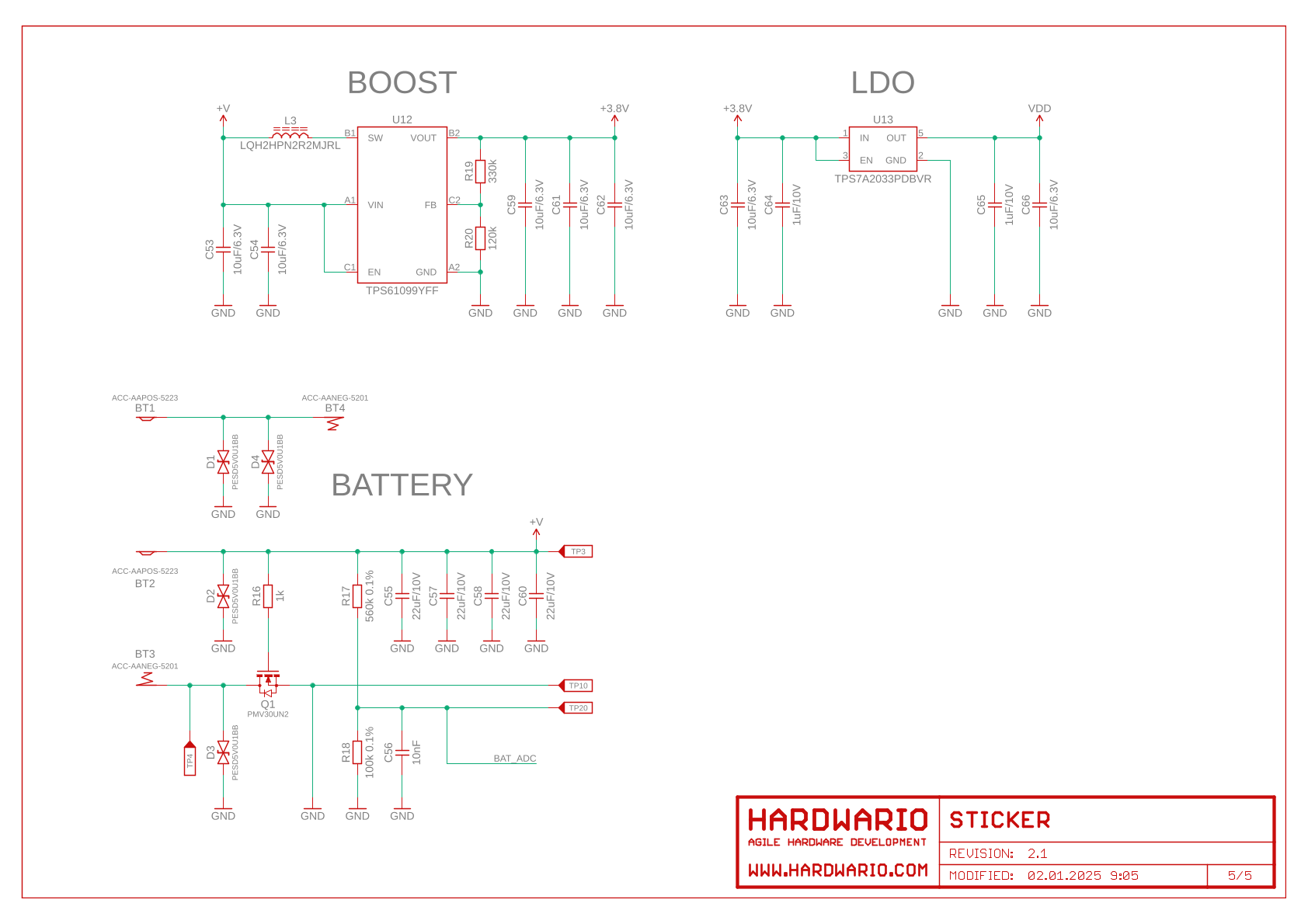
It is powered by two AA batteries, with battery voltage monitoring and efficient power management (boost converter and LDO).
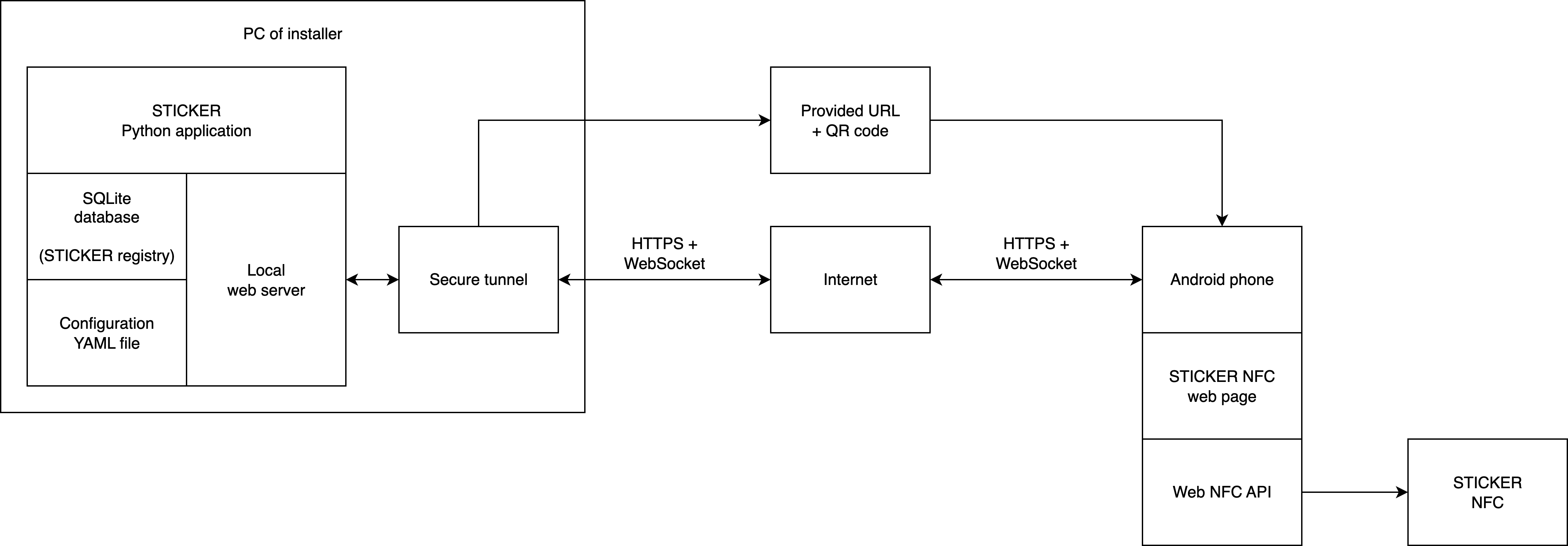
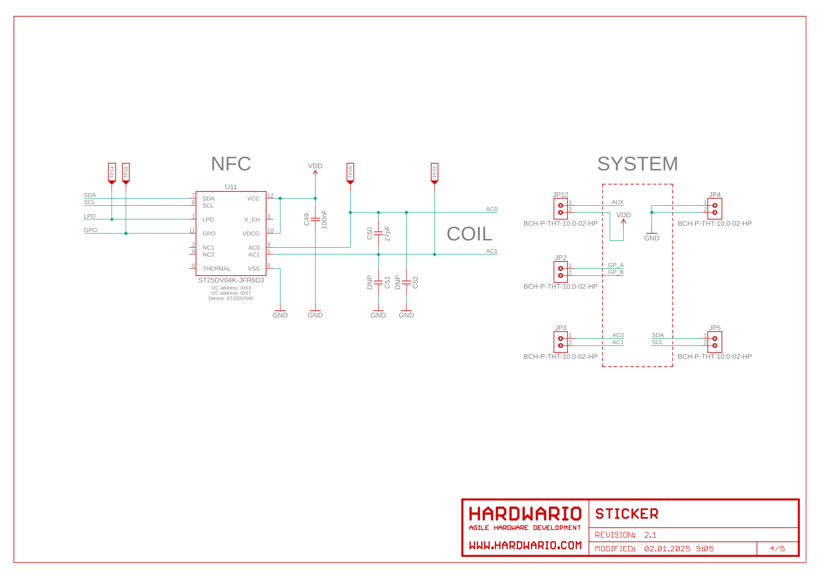
The device includes NFC memory and antenna for simple configuration, even without power (energy harvesting).
Sensors & Peripherals
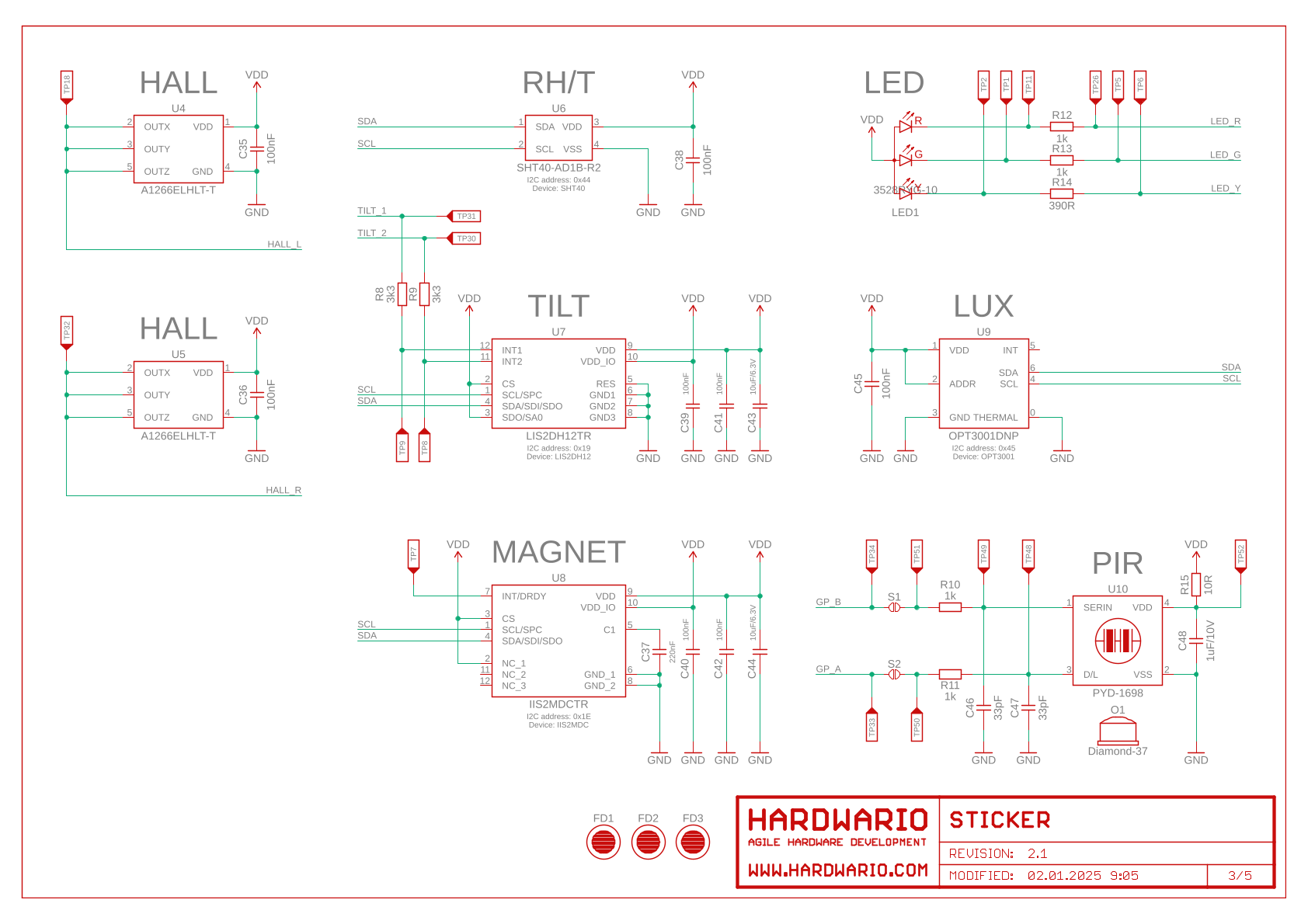
Built-in Sensors
Depending on the specific assembly variant, STICKER includes:
- Temperature & Humidity: Sensirion SHT43 sensor for high-accuracy ambient measurement.
- Light Intensity: Texas Instruments OPT3001 ambient light sensor.
- Atmospheric Pressure: NXP MPL3115A2 pressure sensor.
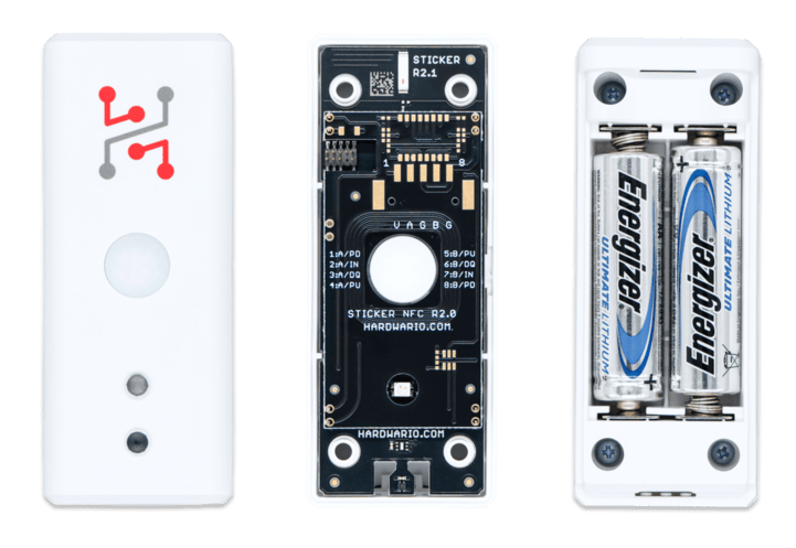
- PIR Motion: Excelitas PYD1698 passive infrared motion sensor for presence detection (up to 5 m, $\ge 50^\circ$).
- 3-axis Accelerometer: STMicroelectronics LIS2DH12 accelerometer for tilt, vibration, and orientation tracking.
- Door Opening Detection: Dual Allegro A1266 Hall-effect sensors.
Physical Interfaces & External Connectivity
- SWD Interface: Physical SWD programming pads for firmware flashing and debugging using J-Link (
make flash). Required for image flashing as the firmware deliberately omits a bootloader and over-the-air updates. - 1-Wire Bus Master: Dedicated 1-Wire interface supporting external digital temperature probes (e.g., Dallas DS18B20) and HARDWARIO Machine Probe sensors.
- S0 Interface: Pulse counting input compatible with standard S0 outputs from electricity, gas, and water meters.
- Voltage Measurement & Industrial Logic Inputs: Supports up to 2 digital inputs accepting industrial logic up to 30 V DC for direct PLC or machine status integration.
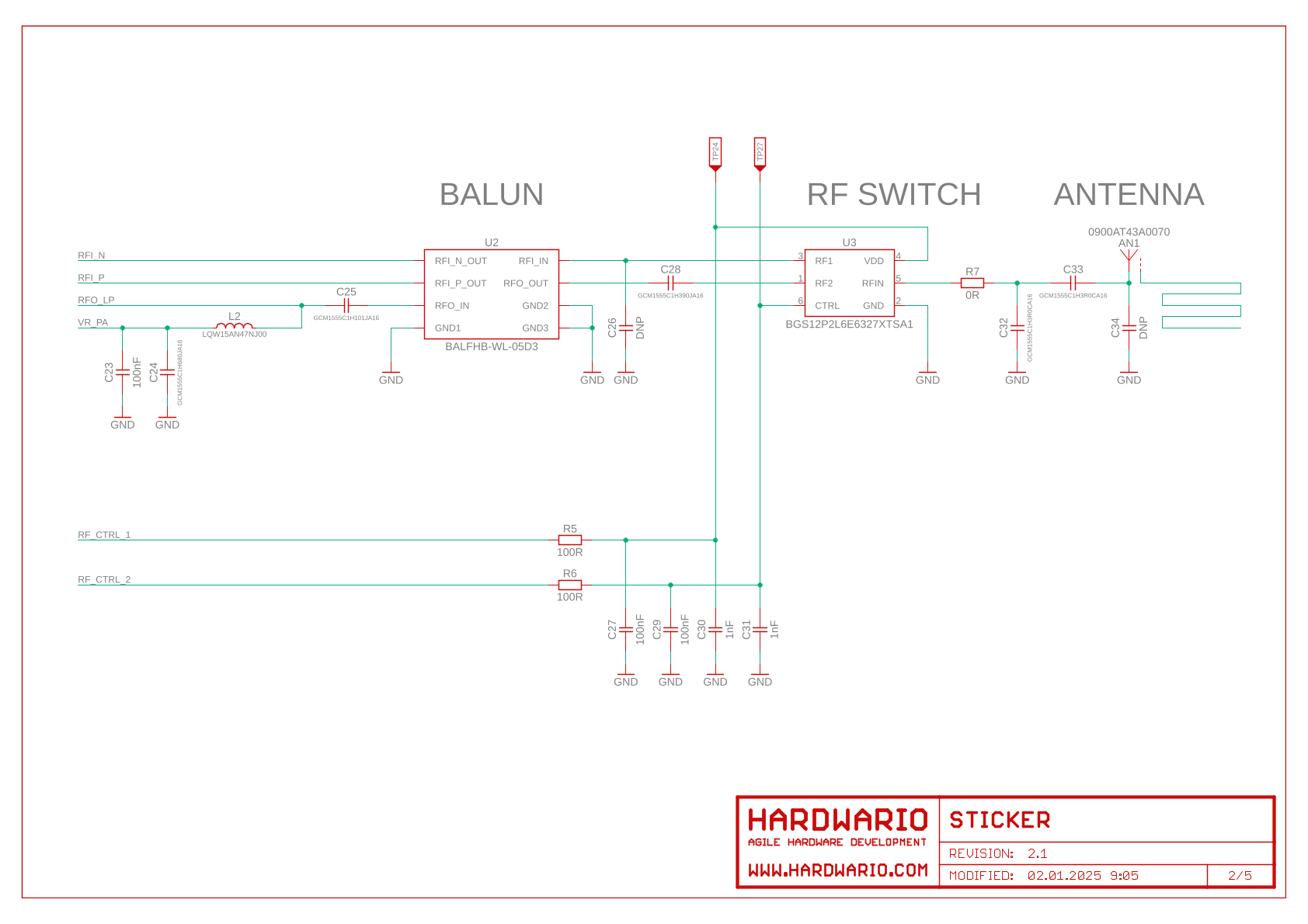
Device status is indicated by a multi-color LED (R/G/Y) - see LED Indication for details - and wireless communication is handled via an internal 868/915 MHz antenna.
Block Diagram
NFC Configuration Architecture
LED Indication
STICKER has one status LED with three independently driven channels - red, green and yellow. The firmware also lights red and green together to produce orange, which it reserves for service modes. The LED is the only feedback the device gives locally, so these patterns are the fastest way to tell what a unit is doing before it appears on the network.
The patterns and timings below apply to firmware v1.4.0. Most status blinks are deliberately very short - 5 to 10 ms - to save battery. Expect a brief blip rather than a comfortable blink.
Boot sequence
Every power-up runs a fixed carousel that also confirms all three channels work:
| Step | Color | Duration |
|---|---|---|
| 1 | Red | 0.5 s |
| 2 | (off) | 0.25 s |
| 3 | Yellow | 0.5 s |
| 4 | (off) | 0.25 s |
| 5 | Green | 1.5 s |
The carousel takes about 5 seconds. If you see it unexpectedly, the device has rebooted.
Status heartbeat
Once running, the device shows its status every 3 seconds. Only one pattern is ever displayed - the firmware checks the conditions below in order and the first match wins, so a more serious condition always hides a less serious one:
| Priority | Device state | LED pattern |
|---|---|---|
| 1 | NFC exchange in progress | The LED is handed over to the NFC patterns below |
| 2 | Configuration could not be loaded - stored settings are corrupt | Red and yellow alternating, twice, ~60 ms each |
| 3 | Joining or rejoining the LoRaWAN network | One yellow flash, then one red flash ~200 ms later |
| 4 | Link degraded - link checks are failing but the session is still alive | Two yellow flashes, ~200 ms apart |
| 5 | Radio switched off by the radio-mode setting | One yellow flash |
| 6 | An alarm is active | One red flash |
| 7 | Normal operation | One green flash |
The three yellow states form a deliberate severity scale, so you can read the seriousness of a network problem from the flash count alone:
radio off (1× yellow) → link degraded (2× yellow) → joining / rejoining (yellow + red)
Priority 2 sits above all of them: a device flashing red/yellow has lost its stored identity and provisioning, and is running on factory defaults. That needs a technician, not a network check.
A device with no green flash is not necessarily faulty - it may simply be busy showing something with a higher priority. Note also that alarms are always evaluated even while a higher-priority pattern owns the LED. Only the red alarm flash is hidden; the alarm itself still triggers and still sends its uplink.
Debug firmware builds replace the single green flash with a green flash followed by a yellow one, which is a quick way to tell a debug unit from a release unit.
NFC interaction
While a phone is held against the device, the LED tracks the exchange step by step:
| What is happening | LED |
|---|---|
| Phone detected in the NFC field | Green, solid |
| Command being processed | Fast green blink (~90 ms) |
| Command rejected - wrong key or token, replayed or malformed request | Fast red blink for 2 s, then off |
| Reply written, waiting for the phone to read it | Green and yellow, solid |
| Exchange finished, phone removed | Off |
| Configuration successfully applied | Ten green blinks, 100 ms on / 100 ms off |
The red rejection blink is worth knowing: without it, a refused command looks exactly like a successful one to whoever is holding the phone.
Input activation
On units with Hall sensors or external inputs configured, the LED confirms each input change. The color order encodes the direction, so an activation cannot be confused with a release:
| Event | Pattern |
|---|---|
| Input becomes active | Green, then orange - 50 ms each |
| Input returns to inactive | Orange, then green - 50 ms each |
Repeated changes are limited to one indication per 500 ms.
This indication switches itself off one hour after power-up. The cutoff is measured from boot, not from the last event, because once a unit is installed the blinking is no longer wanted. If you need it back while testing, power-cycle the device.
PIR and accelerometer are momentary sensors - they only ever report an activation - so on those inputs you will only ever see the green-then-orange sequence.
Calibration mode
| State | Pattern |
|---|---|
| Entering calibration | Five fast orange blinks, 100 ms on / 100 ms off |
| Calibration running | One orange flash every second |
Calibration is entered by holding a magnet to both Hall sensors within 30 minutes of power-up. It runs for 120 minutes and then the device reboots on its own. Orange is used for both states so calibration is never mistaken for one of the yellow network warnings.
Deep sleep
When the device is put into deep sleep, all three channels are switched off. A completely dark LED on a sleeping device is expected and is not a fault.
Testing the LED
The LED can be driven directly over the developer console with the ats led commands - useful for checking a suspect unit. See Diagnostics.
Overview
STICKER Clime - Enclosure, Mainboard, and Battery Holder
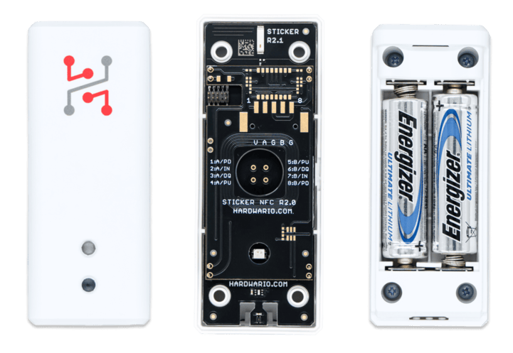
STICKER Input - Enclosure, Mainboard, and Battery Holder
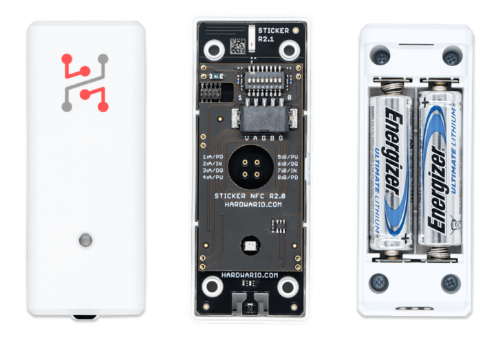
STICKER Motion - Enclosure, Mainboard, and Battery Holder
Hardware Schematics
Power
Download Power Schematic (PDF)
Antenna
Download Antenna Schematic (PDF)
MCU
Sensors
Download Sensors Schematic (PDF)
NFC
Technical Specification
| Category | Parameter | Value |
|---|---|---|
| Structure | Enclosure material | ABS |
| Dimension | 91 × 36.5 × 33.3 mm | |
| Power | Nominal cell voltage | 1.5 V |
| Nominal battery capacity | 3000 mAh | |
| Operating voltage range | 1.8 V to 3.6 V | |
| Idle power consumption | < 80 µA | |
| Peak power consumption | < 100 mA | |
| Environment | Operating temperature | -30 °C to +70 °C |
| Storage temperature | -30 °C to +70 °C | |
| Enclosure protection | IP40 | |
| Sensors | Integrated thermometer – Measurement range | -20 °C to +60 °C |
| Integrated thermometer – Measurement accuracy | ±0.2 °C (0 °C to 65 °C) | |
| Integrated hygrometer – Measurement range | 0 % to 100 % | |
| Integrated hygrometer – Measurement accuracy | ±2 % (from 10 % to 90 %) | |
| PIR – Detection range | 5 m | |
| PIR – Viewing angle | ≥ 50° |