Hardware Description
GLIDER is built around the Nordic nRF9151 system-in-package, a Cortex-M33 microcontroller with an integrated LTE-M / NB-IoT cellular modem. This page summarises the technical details that matter when integrating, wiring or extending the device.
Block diagram
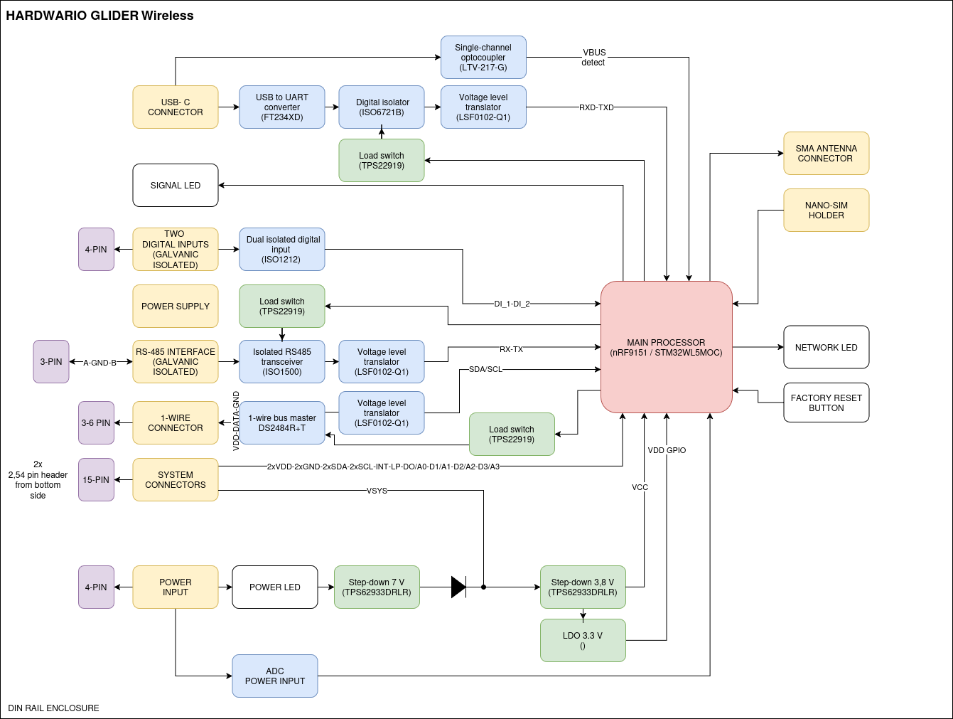
Microcontroller
| SoC | Nordic nRF9151 |
| Core | ARM Cortex-M33 with TrustZone-M |
| Security extensions | TF-M (Trusted Firmware-M) IPC backend, non-secure execution domain (*_ns target) |
| Modem | Integrated LTE-M / NB-IoT |
| Bootloader | MCUboot with dual-image swap (DFU via AT$FW) |
| Watchdog | 120 s hardware watchdog |
The firmware target string used by west build is:
gauger_lte/nrf9151/ns
Pinout
The table below lists every GPIO used by GLIDER, taken from gauger_lte_nrf9151_common.dtsi.
| Pin | Net | Function | Notes |
|---|---|---|---|
| P0.00 | USB_EN | USB bridge power enable | Active high; default off. |
| P0.01 | INT | (Reserved interrupt input) | - |
| P0.02 / P0.03 | I2C3 SDA/SCL | DS2484 1-Wire master | 100 kHz I²C. |
| P0.04 / P0.05 / P0.06 | RS_DE / RS_RE / RS_ON | RS-485 driver enable, receive enable, isolator power | RS_ON active high; default off. |
| P0.07 | SLPZ | DS2484 sleep / wake | Active low. |
| P0.08 / P0.09 / P0.10 | LED_Y / LED_R / LED_G | Yellow / red / green status LEDs | Active high. |
| P0.13 - P0.20 | GP0 - GP7 | General-purpose analog headers | Routable to AIN7 - AIN0. |
| P0.21 | DI_EN | Digital input power enable | Active high; default off. |
| P0.22 / P0.23 | DI_CH0 / DI_CH1 | Isolated digital inputs (CH1 / CH2) | Active high. |
| P0.24 / P0.25 | UART0 RX / TX | USB-C console (via FT234XD) | 1 000 000 baud. |
| P0.26 | USB_DETECT | USB-C cable detection | Active low. |
| P0.27 / P0.28 | UART1 RX / TX | JP5 header debug port | 115 200 baud. |
| P0.29 / P0.30 | UART2 RX / TX | RS-485 (Modbus RTU) via ISO1212DBQ | 19 200 baud, 8E1. |
| P0.31 | BUTTON | User pushbutton | Internal pull-up; active low. |
Connectivity
Cellular
- LTE-M and NB-IoT via the on-board nRF9151 modem.
- nano-SIM slot accessible from the outside.
- LTE bands enabled by default: band 8 and band 20 (Europe). Bands can be reconfigured at build time.
USB-C (AT console)
- USB-C connector → FT234XD USB-UART bridge →
UART0of the nRF9151. - 1 000 000 baud, 8N1.
- The firmware turns the bridge on automatically when it sees
USB_DETECTgo low (50 ms debounce). - See AT Console (USB-C).
J-Link (RTT)
- Standard SWD header (
SWDIO,SWCLK,GND,VTref). - RTT (Real-Time Transfer) provides the Zephyr shell and live log stream.
- See RTT Console (J-Link).
1-Wire (W1, W2)
Two electrically equivalent ports on the screw terminal, both driven by the same Maxim DS2484 1-Wire master on the internal I²C3 bus.
- Up to 8 DS18B20 thermometers can be bound to slots simultaneously.
- Up to 12 devices can be enumerated by
therm scanin a single sweep. - See External Temperature Sensors.
Digital inputs (CH1, CH2)
- 2 galvanically isolated channels routed to
P0.22andP0.23. - Each channel supports
disabled,counterandeventmodes. - Configurable debounce (active / inactive durations) and cooldown between events.
- See Configuration → Digital Inputs.
RS-485 (Modbus RTU)
- Isolated RS-485 transceiver (ISO1212DBQ) on
UART2. - 19 200 baud, 8E1, RTU framing, 500 ms response timeout.
- Powered only when explicitly enabled (
modbus enable) - saves current when idle. - See Shell Commands →
modbus.
Power and timing
| Supply rail | Single 3.3 V (typical for nRF9151) |
| Watchdog timeout | 120 s |
| Default sample period | 60 s (app config interval-sample) |
| Default uplink period | 300 s (app config interval-send) |
| Default downlink watchdog | 36 h (app config downlink-wdg-interval; 0 disables) |
| Peripheral power gating | USB bridge, digital inputs and RS-485 isolator default off - only powered when needed |
Indicators and controls
- LEDs (3): red, green, yellow. Driven by GPIO; controllable via the
ledshell command. - Button (1): drives
app sample/app sendactions depending on click pattern: - 1 click - force
send - 2 clicks - force
sample - 3 clicks -
samplethensend - 4 clicks - reboot the device
Firmware
GLIDER firmware is built on Zephyr / nRF Connect SDK with HARDWARIO's HIO SDK on top, which provides the cloud client, configuration framework, button handling, edge detection and the ATCI interpreter.
Build command:
west build -b gauger_lte/nrf9151/ns application
The internal board name is gauger_lte - GLIDER is the commercial product name; both refer to the same hardware.