CHESTER Control
This article describes the core functionality, hardware description, and example JSON message of the catalog application CHESTER Control.
Some of the basics are not provided, as they are common for all CHESTER catalog applications. Please see:
- Getting started on how to connect device to Cloud.
- Common functionality to know how LED, button and network configuration works.
- Platform Management on how to work with the interactive console.
Application Overview
The application CHESTER Control is used to measure and observe analog and digital inputs. The sampled analog values are aggregated, the aggregate measurements are buffered, and scheduled for later data transfer in the form of buffered data altogether with the timestamp annotations. Also, the changes on digital input (type trigger) can be tracked with the type of change and timestamp. The buffering strategy allows a higher number of events to be recorded while conserving data bandwidth and power required for data transfer.
CHESTER Control has these four inputs:
| Type | Channel | Terminal | Input type | Input range | Typical use-case |
|---|---|---|---|---|---|
| Trigger | CH1 | A2 | Digital - NPN/PNP | 0 to 28 V | Switch, button, relay, PLC sensor |
| Counter | CH2 | A4 | Digital - NPN/PNP | 0 to 28 V | Energy meter pulse outputs (e.g., S0) |
| Voltage | CH3 | A5 | Analog - voltage | 0 to 28 V | Various voltage transmitters |
| Current | CH4 | A7 | Analog - current | 0 to 24 mA | Various current transmitters |
All these inputs and their options are explained in more detail in the article Input Parameters and Behavior.
Additionally, CHESTER Control allows remote control of 4 digital (6-28 V) outputs.
Application Variants
CHESTER Control can be ordered in one of these variants:
CHESTER Control
The catalog CHESTER Control hardware consists of the following ordering codes:
-
CHESTER-M-BCGLS- Standard mainboard -
CHESTER-X0B:A- Input module (4 channels) -
CHESTER-X4:B- Step-down + outputs (4 channels)
See Ordering Codes for more details.
CHESTER Control Z
The catalog CHESTER Control Z hardware consists of the following ordering codes:
-
CHESTER-M-BCGLS- Standard mainboard -
CHESTER-X0B:A- Input module (4 channels) -
CHESTER-X4:B- Step-down + outputs (4 channels) -
CHESTER-Z1- Backup module
See Ordering Codes for more details.
Terminal Blocks
| CHESTER-X0B in left slot A- signals A1 - A8 | CHESTER-X4 in right slot B - signals B1 - B8 |
|---|---|
| Use inputs CH1 to CH4 and GND | Use VIN and GND to supply external power. |
| Use CH1 to CH4 outputs, which supply voltage from VIN when the output is enabled | |
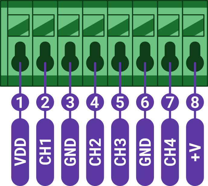 | 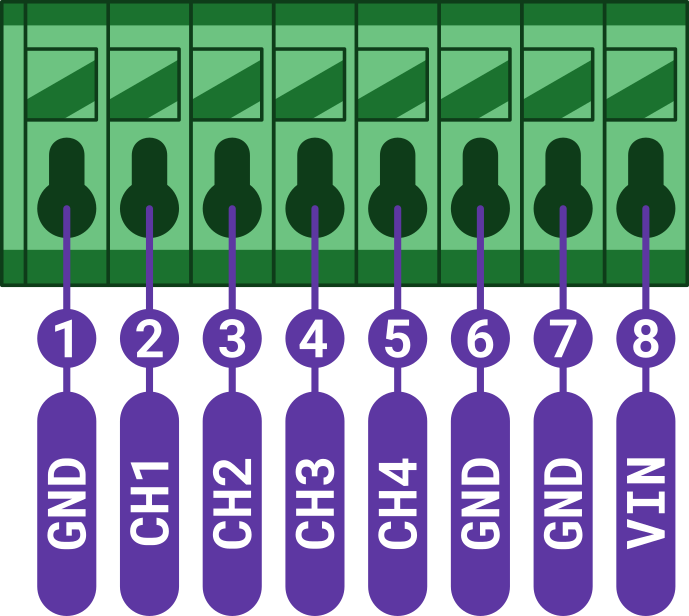 |
Input Parameters and Behavior
For the wiring diagram of CHESTER Control, please follow the terminal block description of the CHESTER-X0 extension module. The extension module CHESTER-X0 is installed in the left slot A, so you have to use the corresponding terminals A1 to A8.
Trigger
The trigger input can be connected to a PLC/sensor output (NPN/PNP), push button, switch, relay, etc. The behavior of the trigger input is configurable.
-
When the input changes, the timestamp of the change event is stored altogether with the active/inactive state, this information is buffered, and the buffer of the events is sent (at the latest) with the regular report (parameter
interval-report). -
Optionally, input changes to the active (parameter
trigger-report-active) or inactive (parametertrigger-report-inactive) states can be reported immediately or with a configurable delay (parameterevent-report-delay) to allow capturing multiple consequent input changes. -
Both NPN and PNP input logic types are supported (parameter
trigger-input-type). -
The minimum level duration is configured separately for active (parameter
trigger-duration-active) and inactive (parametertrigger-duration-inactive) states. -
The maximum number of reports per hour is configurable (parameter
event-report-rate). The event throttling limits communication bandwidth and preserves the battery lifespan.
Counter
The counter input can be connected to a PLC/sensor output (NPN/PNP), push button, switch, relay, etc. This input counts the total number of pulses in time.
-
The counter value is aggregated periodically (parameter
counter-interval-aggreg), and the buffer of aggregated measurements is reported in a configurable interval (parameterinterval-report). -
Both NPN and PNP type of input logic is supported (parameter
counter-input-type). -
The minimum level duration is configured separately for active (parameter
counter-duration-active) and inactive (parametercounter-duration-inactive) states.
Voltage
The voltage input measures the voltage in the range from 0-28 V (overlaps the 0-10 V standard).
-
The voltage readings are sampled periodically (parameter
analog-interval-sample). These readings are stored as a buffer of samples. -
The collected samples are aggregated periodically (parameter
analog-interval-aggreg). The minimum, maximum, average, and median aggregates are computed from the buffered samples. These aggregated results are referred to as measurements. -
Each measurement has an associated timestamp. The buffer measurements are transferred as time-series data regularly (parameter
interval-report).
Current
This input measures the analog current in the range from 0-24 mA (overlaps the 4-20 mA standard).
-
The current readings are sampled periodically (parameter
analog-interval-sample). These readings are stored as a buffer of samples. -
The collected samples are aggregated periodically (parameter
analog-interval-aggreg). The minimum, maximum, average, and median aggregates are computed from the buffered samples. These aggregated results are referred to as measurements. -
Each measurement has an associated timestamp. The buffer measurements are transferred as time-series data regularly (parameter
interval-report).
Backup
CHESTER Control Z (equipped with CHESTER-Z1) can also report information on the backup battery and external DC power state.
-
The current battery voltage and external DC voltage are sent in every report.
-
When the DC power input changes, the timestamp of the change event is stored altogether with the connected/disconnected state, this information is buffered, and the buffer of the events is sent (at the latest) with the regular report (parameter
interval-report). -
Optionally, DC power input changes to the connected (parameter
backup-report-connected) or disconnected (parameterbackup-report-disconnected) states can be reported immediately or with a configurable delay (parameterevent-report-delay) to allow capturing multiple consequent input changes. -
The maximum number of reports per hour is configurable (parameter
event-report-rate). The event throttling limits communication bandwidth and preserves the battery lifespan.
Hygrometer
The optional hygrometer in the CHESTER Control application represents an external temperature and humidity sensor.
-
The readings are sampled regularly (parameter
hygro-interval-sample). These readings are stored as a buffer of samples. -
The collected samples are aggregated periodically (parameter
hygro-interval-aggreg). The minimum, maximum, average, and median aggregates are computed from the buffered samples. These aggregated results are referred to as measurements. -
Each measurement has an associated timestamp. The buffer measurements are transferred as time-series data regularly (parameter
interval-report).
Default Configuration
This is the default configuration (printed using the app config show command):
app config interval-report 1800
app config interval-poll 0
app config downlink-wdg-interval 129600
app config event-report-delay 5
app config event-report-rate 30
app config channel-mode-1 "trigger"
app config channel-mode-2 "counter"
app config channel-mode-3 "voltage"
app config channel-mode-4 "current"
app config trigger-input-type "npn"
app config counter-input-type "npn"
app config trigger-duration-active 100
app config trigger-duration-inactive 100
app config trigger-cooldown-time 10
app config trigger-report-active false
app config trigger-report-inactive false
app config counter-interval-aggreg 300
app config counter-duration-active 2
app config counter-duration-inactive 2
app config counter-cooldown-time 10
app config analog-interval-sample 60
app config analog-interval-aggreg 300
app config w1-therm-interval-sample 60
app config w1-therm-interval-aggreg 300
app config mode "lte"
Specific Commands
You can easily explore the whole command tree structure - start with the help command.
Use this command to set report interval (in seconds):
app config interval-report <value>
Use this command to configure a short delay (in seconds) between the trigger or backup event and its reporting:
app config event-report-delay <value>
This feature is useful in systems where another change may arrive shortly after the first one.
Use this command to limit the number of asynchronous trigger or backup event reports in a one-hour window:
app config event-report-rate <value>
This feature helps to conserve power in the battery-operated device and optimizes the amount of transferred data. The regular (periodic) reports set by the parameter interval-report are not counted to this limit.
Use these commands to enable/disable reporting of the backup module power input connect/disconnect events:
app config backup-report-connected false
app config backup-report-disconnected false
Use these commands to set the input type for trigger and counter inputs. The valid values are npn or pnp:
app config trigger-input-type <npn/pnp>
app config counter-input-type <npn/pnp>
Use these commands to enable/disable trigger input to immediately report a change to active or inactive levels:
app config trigger-report-active <true/false>
app config trigger-report-inactive <true/false>
Use these commands to set the active and inactive time duration (in milliseconds) for the trigger and counter digital inputs:
app config trigger-duration-active <value>
app config trigger-duration-inactive <value>
app config trigger-cooldown-time <value>

app config counter-duration-active <value>
app config counter-duration-inactive <value>
app config counter-cooldown-time <value>
- The parameter
duration-activesets the millisecond delay between the input signal changes to an active level (based onnpnorpnpconfiguration) and when CHESTER reacts to this change. This could be used to filter (debounce) input signal in case the input signal is connected to a "electrically noisy" mechanical switch or relay. It could also be used if the CHESTER has to react to longer pulses than the set duration. - The parameter
duration-inactiveis the same as for theduration-activeabove, except it sets the time for the opposite edge. - The parameter
cooldown-timeis a delay protecting CHESTER from too many incoming interrupt events. If a too-fast signal (>10 kHz) is connected, the interrupt handler could consume all the processor time, stopping the execution of other threads. This parameter sets a small delay between executing the interrupt handler again. A default value of 10 ms could be used here.
Use these commands to set the sample and aggregate intervals (in seconds) for voltage / current measurements:
app config analog-interval-sample <value>
app config analog-interval-aggreg <value>
Use these commands to set the sample and aggregate intervals (in seconds) for the optional hygrometer (the accessory CHESTER-S2):
app config hygro-interval-sample <value>
app config hygro-interval-aggreg <value>
Output Control
Please see the Cloud documentation, specifically Downlink data and API examples.
You control outputs by sending this JSON to the cloud API endpoint (https://api.prod.hardwario.cloud/v2/messages) or in the HARDWARIO Cloud by going to the device's messages and clicking on "Create new downlink message"
{
  "output_1_state": 1,
  "output_2_state": 1,
  "output_3_state": 0,
  "output_4_state": 0
}
The JSON doesn't have to contain the output state of all four outputs. You send only output_X_state for outputs to be changed.
The device is polling the Cloud in an interval set by interval-poll parameter and if a new downlink control message is in the Cloud queue, it is sent to the device and output or multiple outputs are changed.
Example JSON Message
- LTE
- LoRaWAN
Show JSON Example
{
    "accelerometer": {
        "accel_x": 0,
        "accel_y": 0,
        "accel_z": 9.57,
        "orientation": 2
    },
    "counter": [
        {
            "channel": 2,
            "delta": 6,
            "measurements": [
                {
                    "timestamp": 1705328041,
                    "value": 4,
                    "delta": 2
                },
                {
                    "timestamp": 1705328341,
                    "value": 7,
                    "delta": 3
                }
            ],
            "value": 7
        }
    ],
    "current": [
        {
            "channel": 4,
            "measurements": [
                {
                    "avg": 2,
                    "max": 5.03,
                    "mdn": 0,
                    "min": 0,
                    "timestamp": 1705328341
                }
            ]
        }
    ],
    "message": {
        "sequence": 1,
        "timestamp": 1705328341,
        "version": 1
    },
    "network": {
        "imei": 351358816128174,
        "imsi": 901288910100358
    },
    "thermometer": {
        "temperature": 22.75
    },
    "trigger": [
        {
            "channel": 1,
            "events": [
                {
                    "timestamp": 1705328233,
                    "type": "activated"
                },
                {
                    "timestamp": 1705328233,
                    "type": "deactivated"
                },
                {
                    "timestamp": 1705328233,
                    "type": "activated"
                },
                {
                    "timestamp": 1705328233,
                    "type": "deactivated"
                },
                {
                    "timestamp": 1705328234,
                    "type": "activated"
                },
                {
                    "timestamp": 1705328234,
                    "type": "deactivated"
                },
                {
                    "timestamp": 1705328234,
                    "type": "activated"
                },
                {
                    "timestamp": 1705328235,
                    "type": "deactivated"
                }
            ],
            "state": "inactive"
        }
    ],
    "voltage": [
        {
            "channel": 3,
            "measurements": [
                {
                    "avg": 0.27,
                    "max": 1.35,
                    "mdn": 0,
                    "min": 0,
                    "timestamp": 1705328341
                }
            ]
        }
    ]
}
Show JSON Example
{
  "voltage_rest": 3.7,
  "voltage_load": 3.65,
  "current_load": 20,
  "orientation": 2,
  "therm_temperature": 23.5,
  "hygro_temperature": 23.2,
  "hygro_humidity": 48.5,
  "w1_thermometers": [22.1, 22.3],
  "ble_tags": [
    {
      "temperature": 21.5,
      "humidity": 55.0
    }
  ],
  "inputs_a": [
    {
      "type": "trigger",
      "state": true,
      "trigger_active": 5,
      "trigger_inactive": 3
    },
    {
      "type": "counter",
      "count": 1234,
      "delta": 12
    },
    {
      "type": "voltage",
      "voltage": 12.5
    },
    {
      "type": "current",
      "current": 4.2
    }
  ]
}
Changelog
v3.5.5 — 2026-06-22
- Changed: Reduced memory footprint — soil sensor and thermometer data now dynamically allocated
v3.5.0 — 2025-12-03
- Added: LoRaWAN support — single firmware binary for both LTE and LoRaWAN; mode selectable via
app config mode lte/app config mode lrw - Added: Downlink watchdog interval (
downlink-wdg-interval) to detect loss of cloud communication - Added: Configurable poll interval (
interval-poll) for cloud polling frequency - Changed: Cloud v2 protocol adopted (CBOR encoding, new API endpoints); previous Cloud v1 firmware remains separately available
- Changed: Channel modes now explicitly configurable per channel (
channel-mode-1throughchannel-mode-4)
For a complete overview of all platform changes, see the CHESTER Changelog.